
Optimizing Algorithm for Controlling Drill String Driver

a technology of optimizing algorithm and drill string, which is applied in the direction of automatic control of drilling, drilling accessories, earth-moving drilling and mining, etc., can solve the problems of bit wear, one or more of reduced penetration rate through subterranean formation, and complicated dynamic behavior of drill string, so as to reduce the amplitude of rotational waves travelling and reduce the rotational waves travelling

Pending Publication Date: 2021-05-06
SCHLUMBERGER TECH CORP
View PDF13 Cites 1 Cited by
  • Summary
  • Abstract
  • Description
  • Claims
  • Application Information

AI Technical Summary

Benefits of technology

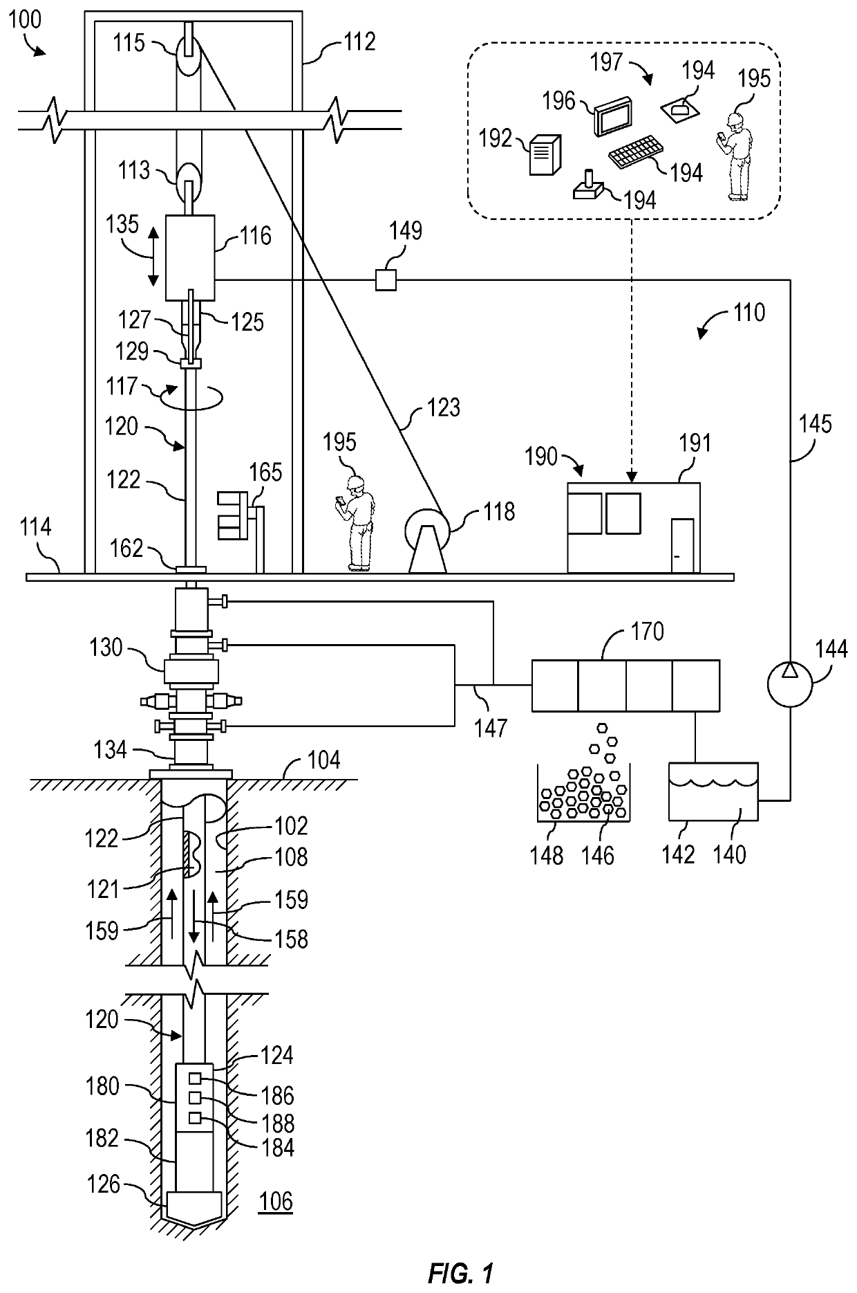
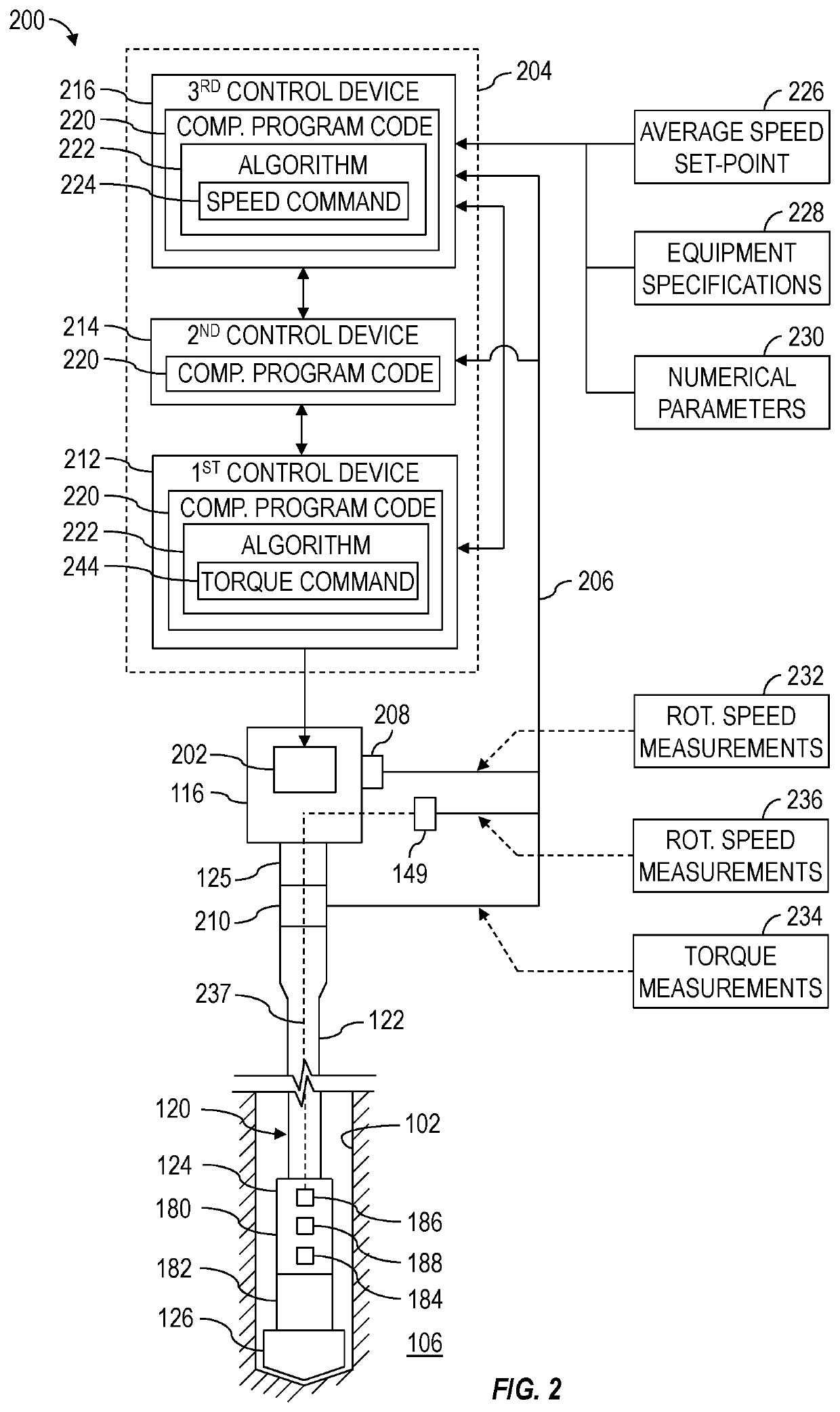
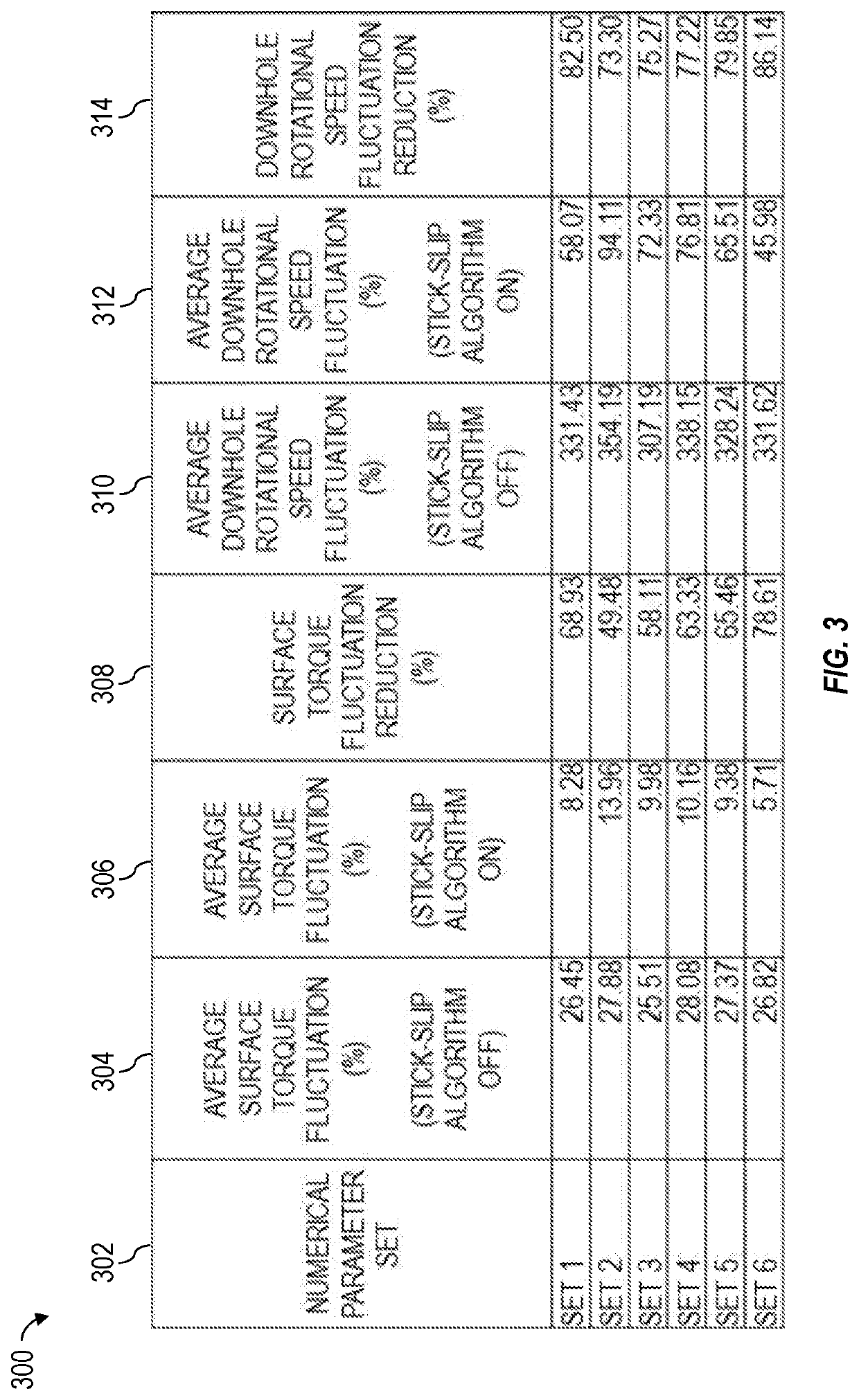
The present patent introduces a method for controlling a drill string driver using a control system that includes a processor and a memory storing a computer program code. The computer program code includes a stick-slip algorithm that takes into account different numerical parameters to determine a control command that causes the driver to rotate the drill string to perform drilling operations while reducing rotational waves traveling along the drill string. The present patent also introduces a method for running a computer simulation of a drill string being rotated by a driver to drill a wellbore, where the driver's rotation is controlled using the stick-slip algorithm to reduce the amplitude of rotational waves traveling along the drill string.

Problems solved by technology

During drilling operations, a drill string undergoes complicated dynamic behavior, including experiencing axial, lateral, and rotational vibrations, as well as frictional interactions with the bottom and sidewalls of the wellbore being drilled.
Stick-slip motion and the resulting rotational waves in the drill string are a recognized problem in the drilling industry, causing one or more of reduced rate of penetration through the subterranean formation, bit wear, torsional damage to the drill string, failures or damage to the surface driver, and other damage to drilling equipment.

Method used


Image

  • Optimizing Algorithm for Controlling Drill String Driver
  • Optimizing Algorithm for Controlling Drill String Driver
  • Optimizing Algorithm for Controlling Drill String Driver

Examples


Embodiment Construction

[0015]It is to be understood that the following disclosure provides many different embodiments, or examples, for implementing different features of various embodiments. Specific examples of components and arrangements are described below to simplify the present disclosure. These are, of course, merely examples and are not intended to be limiting. In addition, the present disclosure may repeat reference numerals and / or letters in the various examples. This repetition is for simplicity and clarity, and does not in itself dictate a relationship between the various embodiments and / or configurations discussed.

[0016]Systems and methods (e.g., processes, operations, etc.) according to one or more aspects of the present disclosure may be used or performed in association with a well construction system at a wellsite, such as for constructing a wellbore to obtain hydrocarbons (e.g., oil and / or gas) or other natural resources from a subterranean formation. A person having ordinary skill in the...


PUM


Abstract

Apparatus and methods for optimizing a stick-slip algorithm for controlling a driver of a drill string. A method may include commencing operation of a control system for controlling the driver. The control system may have a processor and a memory storing a computer program code, which may include the stick-slip algorithm. The operating control system may receive a plurality of different numerical parameters, and for each of the different numerical parameters, incorporate the numerical parameter into the stick-slip algorithm and execute the stick-slip algorithm to determine a control command that causes the driver to rotate the drill string to perform drilling operations while reducing amplitude of rotational waves travelling along the drill string.

Description

CROSS-REFERENCE TO RELATED APPLICATIONS[0001]This application claims priority to and the benefit of U.S. Provisional Application No. 62 / 930,045, titled “Optimizing Algorithm for Controlling Drill String Driver,” filed Nov. 4, 2019, the entire disclosure of which is hereby incorporated herein by reference.BACKGROUND OF THE DISCLOSURE[0002]Wells are generally drilled into the ground or ocean bed to recover natural deposits of oil, gas, and other materials that are trapped in subterranean formations. Drilling operations may be performed at a wellsite by a well construction system (i.e., a drilling rig) having various surface and subterranean well construction equipment being operated in a coordinated manner. For example, a driver (i.e., a drive mechanism), such as a top drive or a rotary table located at a wellsite surface, can be utilized to rotate and advance a drill string into a subterranean formation to drill a wellbore. The drill string may include a plurality of drill pipes coup...

Claims


Application Information

Patent Timeline
Patent Type & Authority Applications(United States)
IPC IPC(8): E21B44/04
CPCE21B44/04E21B44/08
Inventor JEFFRYES, BENJAMIN PETERWICKS, NATHANIELWU, JIAN
Owner SCHLUMBERGER TECH CORP
Learn More