Low Loss Reflective Passive Phase Shifter using Time Delay Element with Double Resolution

a phase shifter and time delay technology, applied in the field of phase shifters, can solve the problems of dc power, lower power handling capability, and disadvantages of being uni-directional, and achieve the effect of increasing the resolution of the phase shifter

Active Publication Date: 2021-05-06
PSEMI CORP
View PDF1 Cites 0 Cited by
  • Summary
  • Abstract
  • Description
  • Claims
  • Application Information

AI Technical Summary

Benefits of technology

[0018]In some embodiments, the transistors are tapered in size along the length of the ATLs to provide a more consistent insertion loss as various phase shifts are selected. In some such embodiments, the distance between a ground trace and the central trace is also tapered along the length of the ATL to compensate for differences in the capacitance of the tapered transistors. In addition, some embodiments have an integrated digital switched attenuator that allows selective attenuation of the signal, as well as selective phase shifting.
[0019]In some embodiments, transistors are placed on each side of the central trace and aligned in pairs. Each transistor of a pair is turned on and off together. In other embodiments, the transistors on each side of the central trace are offset from one another with respect to their distance to the reflective port to which the ATL is coupled. Accordingly, the resolution of the phase shifter can be increased by providing twice the number of selectable electrical lengths along the ATL.

Problems solved by technology

However, these advantages come at the expense of being uni-directional, requiring DC power, being less linear, having lower power handling capability and being less stable in high volume production.

Method used


Image

  • Low Loss Reflective Passive Phase Shifter using Time Delay Element with Double Resolution
  • Low Loss Reflective Passive Phase Shifter using Time Delay Element with Double Resolution
  • Low Loss Reflective Passive Phase Shifter using Time Delay Element with Double Resolution

Examples


Embodiment Construction

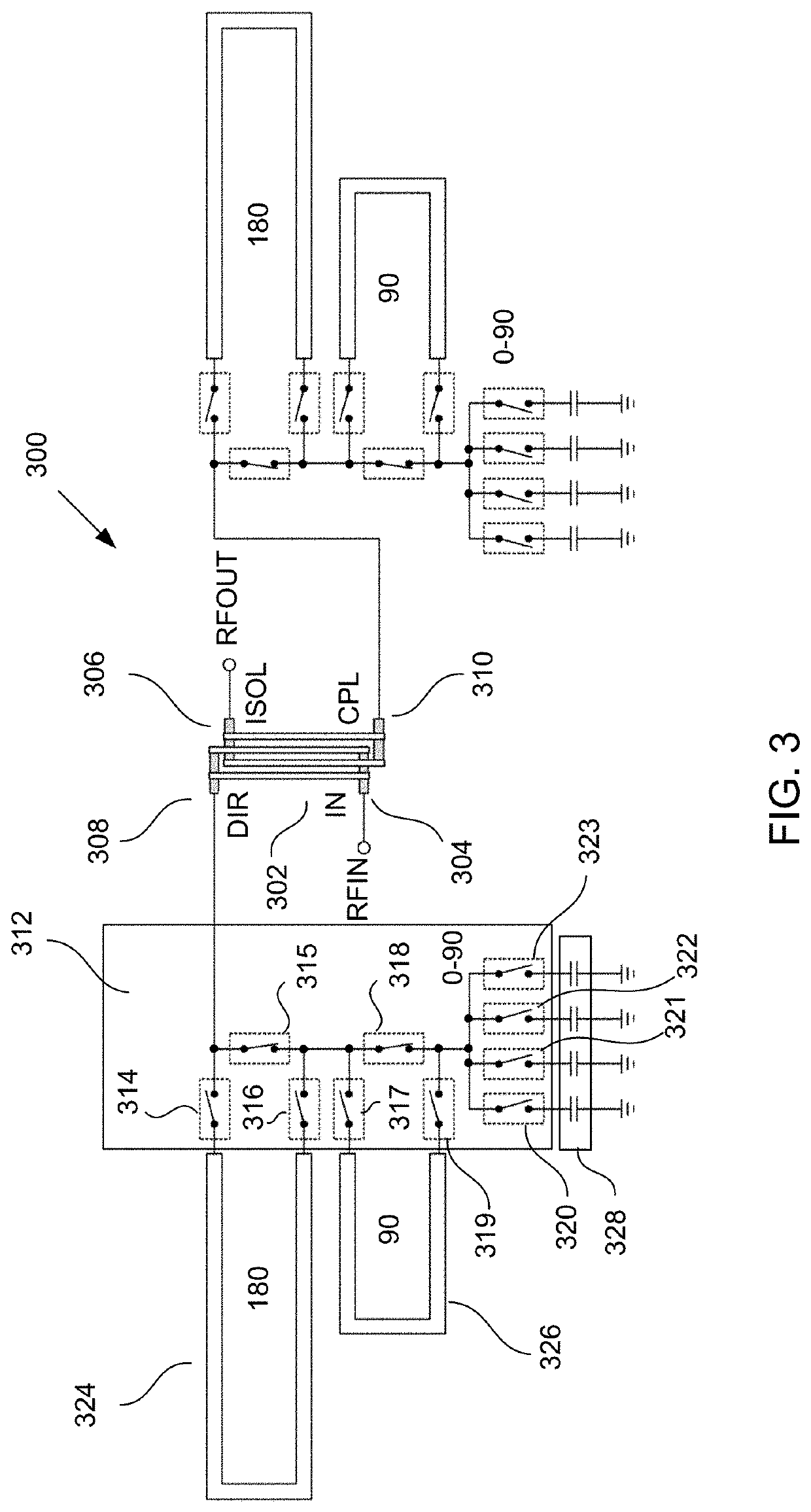
[0050]FIG. 3 is an illustration of a reflection phase shifter 300 using a Lange coupler. The Lange coupler 302 has four ports: an input port 304, an isolation (output) port 306, a direct port 308 and a coupled port 310. The direct port 308 and the coupled port 310 are each terminated. However, the termination is provided through a network 312 of switches that determine the nature of the path between each port 308, 310 and ground.

[0051]The path to ground for both the direct port 308 and the coupled port 310 are essentially identical. Accordingly, for the sake of simplicity, only the path from the direct port 308 is described in detail at this time. However, it should be understood that the description of the path from the direct port 308 to ground applies equally to the path from the coupled port 310 to ground.

[0052]The direct port 308 is coupled to a first terminal of a “180° / in switch”314 and a “180° bypass switch”315 within a switch network 312. The second terminal of the 180° / in ...


PUM


Abstract

A phase shifter for altering the phase of a radio frequency signal is disclosed herein. A Lange coupler is used having reflective ports that are coupled to artificial transmission lines. The artificial transmission lines provide a reflection transmission path, the length of which can be determined by digital control lines. Transistors placed along the length of the central trace provide independent paths to ground that serve to shorten the electrical length of the ATL. Accordingly, by selectively turning the transistors on / off, the electrical length of the ATL can be selected and thus the amount of phase delay introduced by the phase shifter.

Description

CROSS-REFERENCE TO RELATED APPLICATIONS—CLAIM OF PRIORITY[0001]The present application is a continuation of, and claims priority to, co-pending and commonly assigned U.S. patent application Ser. No. 16 / 372,194, filed Apr. 1, 2019, entitled “Low Loss Reflective Passive Phase Shifter using Time Delay Element with Double Resolution”, the entire contents of which is incorporated herein by reference, which is a continuation-in-art of, and claims priority to, commonly assigned U.S. patent application Ser. No. 16 / 052,337, filed Aug. 1, 2018, entitled “Low Loss Reflective Passive Phase Shifter using Time Delay Element”, now abandoned, the entire contents of which is incorporated herein by reference, which application is a continuation-in-part of, and claims priority to, commonly assigned U.S. patent application Ser. No. 14 / 988,463, filed Jan. 5, 2016, entitled “Reflection-Based RF Phase Shifter”, now U.S. Pat. No. 10,062,946 issued Aug. 28, 2018, the entire contents of which is incorporated...

Claims


Application Information

Patent Timeline
Patent Type & Authority Applications(United States)
IPC IPC(8): H03H11/20H03H11/26H03H17/08H03H17/00
CPCH03H11/20H03H11/265H03H17/0009H03H17/0054H03H17/08H01P1/184H03H7/20H03H7/18
Inventor BIRKBECK, JOHNSHARMA, VIKASPAL, KASHISHO'LEARY, MARK JAMES
Owner PSEMI CORP
Why Eureka
Try Eureka