Apparatus for detecting particles

a particle detection and apparatus technology, applied in the field of particles detection devices and mass spectrometers, can solve the problem that particles which strike these gaps cannot be detected, and achieve the effect of simple and inexpensive production, large aspect ratio of structures

Inactive Publication Date: 2009-03-31
SPECTRO ANALYTICAL INSTR
View PDF7 Cites 6 Cited by
  • Summary
  • Abstract
  • Description
  • Claims
  • Application Information

AI Technical Summary

Benefits of technology

[0013]In a generally preferred embodiment the structures are produced by means of a microprocessing process, in particular a

Problems solved by technology

Particles which strike these gaps cannot be detected as

Method used


Image

  • Apparatus for detecting particles
  • Apparatus for detecting particles

Examples


Embodiment Construction

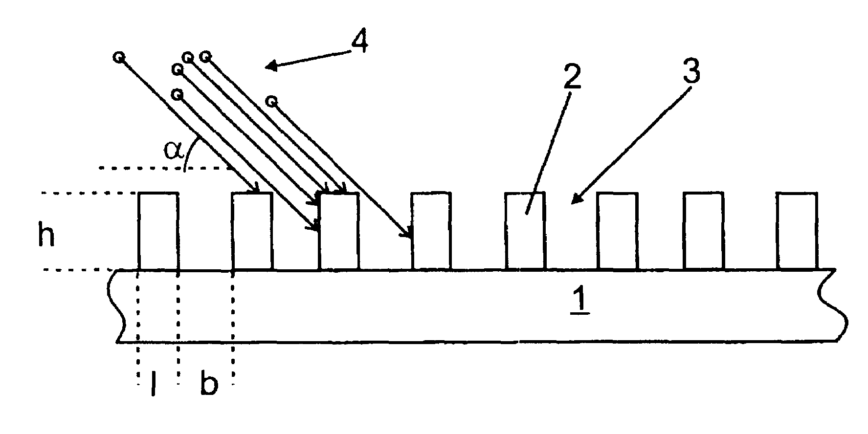
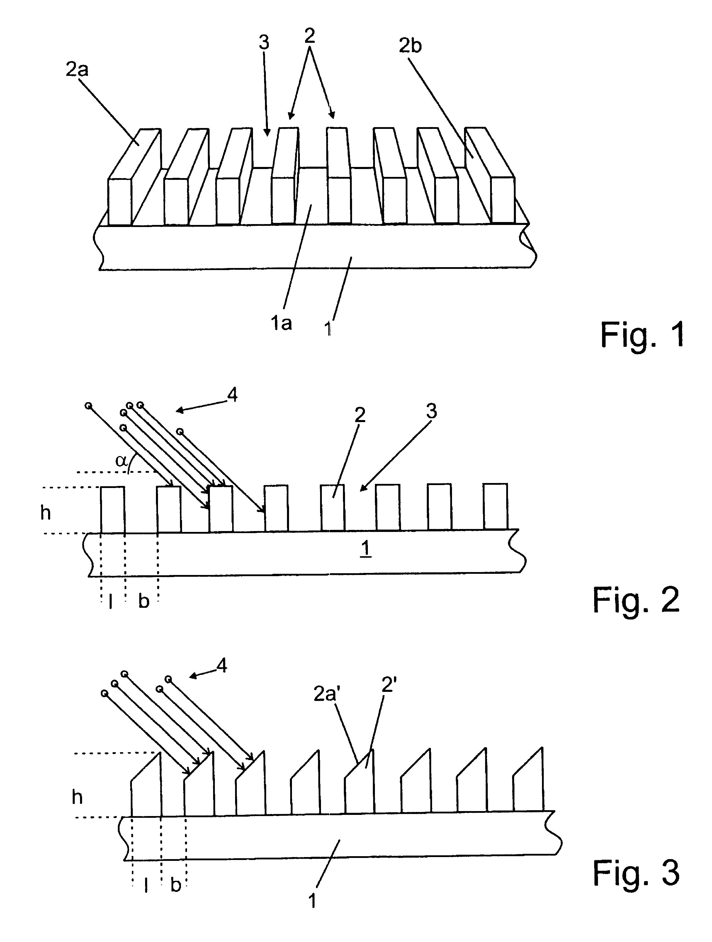
[0020]FIG. 1 shows an apparatus for detecting particles which comprises a support element 1 with a surface 1a extending in one plane. The support element 1 can, in particular, consist of an insulating material. A plurality of elongated structures 2 which consist of a conductive material are located on the support element 1. The structures 2 are electrically insulated with respect to the support element 1. The insulation is provided either in that the support element 1 is insulating as a whole or by an insulating layer (not shown) located between the structures 2 and the support element 1.

[0021]In the present case the structures 2 are prisms with a rectangular cross-section and are uniform in each case. They each have a length l and a height h. A trough 3, which is not filled with material and has a width b, is located between two of the structures 2 in each case.

[0022]Each of the structures 2 is separately electrically connected to an electronic read-out device (not shown). The elec...


PUM


Abstract

An apparatus for detecting particles, comprising a plurality of electrically conductive structures disposed on a support element. The structures are electrically insulated from one another and each structure can be electrically connected to an electronic read-out device. The structures receive a beam of particles in a direction forming an angle of incidence with the support element. A trough is disposed between each two successive structures as viewed in the beam direction. And at least partial overlap exists between each two successive structures. The apparatus can be disposed in the focal plane of a mass spectrometer.

Description

BACKGROUND OF THE INVENTION[0001]The present invention relates to a device for detecting particles and to a mass spectrometer.[0002]It is known to detect particles by means of spatially resolved detectors which comprise a number of contacted elements on which the particles directly strike and can be electrically detected. In this case the particles may either be charged particles which directly generate an electrical signal owing to their charge, or protons or other uncharged particles which bring about an electrical signal as a result of appropriate interaction with an existing element coating.[0003]US 2004 / 0222374 A1 describes a spatially resolved detector in which a large number of strip-like, conductive elements is arranged side by side in one plane. The elements are separately contacted by an electronic read-out device. The surfaces of the elements are all located in one plane, wherein gaps of non-contacted material remain between the elements. Particles which strike these gaps...

Claims


Application Information

Patent Timeline
IPC IPC(8): G01T1/00
CPCH01J49/025
Inventor SCHEIDEMANN, ADI A.ARDELT, DIRKDENTON, M. BONNER
Owner SPECTRO ANALYTICAL INSTR
Why Eureka
Try Eureka