Tool, a machine, and a method for orbitally drilling an orifice

a technology of orbital drilling and orifice, which is applied in the direction of driving apparatus, attachable milling devices, manufacturing tools, etc., can solve the problems of shape and precision of orifices, and the above-specified type of tools are poorly adapted to making orifices having a large length/diameter ratio, and achieves the effect of large length/diameter

Inactive Publication Date: 2004-11-23
APEX BRANDS
View PDF15 Cites 29 Cited by
  • Summary
  • Abstract
  • Description
  • Claims
  • Application Information

AI Technical Summary

Benefits of technology

An object of the invention is to solve that problem by providing a tool of the above-specified type which makes it possible to make orifices having a large length / diameter ratio.

Problems solved by technology

While drilling is taking place, the cutter is thus cantilevered out and is subjected to high bending forces which can harm, in particular, the shape and the precision of the orifices that are obtained.
Thus, tools of the above-specified type are poorly adapted to making orifices having a large length / diameter ratio.

Method used


Image

  • Tool, a machine, and a method for orbitally drilling an orifice
  • Tool, a machine, and a method for orbitally drilling an orifice
  • Tool, a machine, and a method for orbitally drilling an orifice

Examples


Embodiment Construction

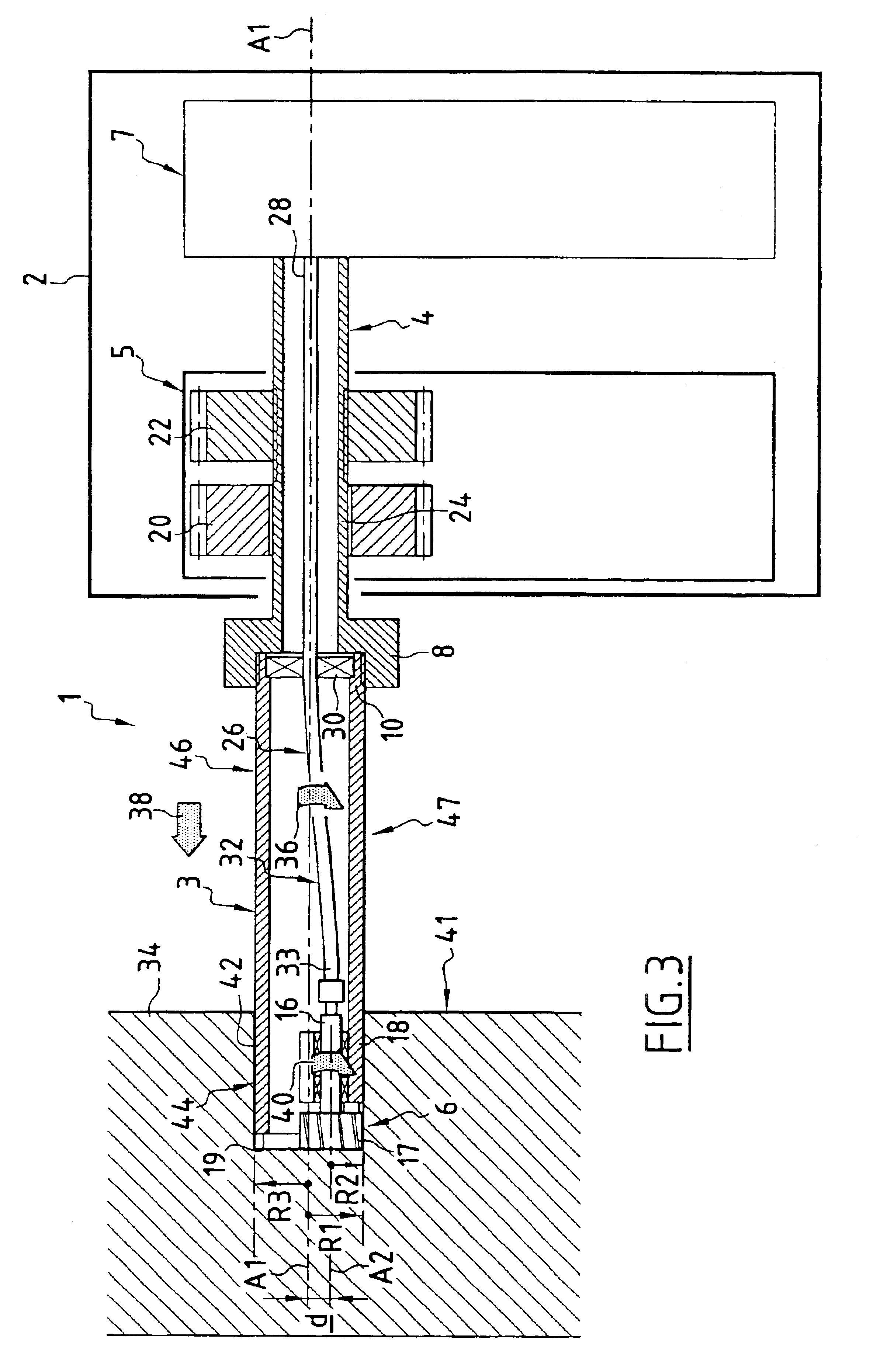
Below, the terms "front" and "rear" are used relative to the direction in which an orifice is drilled in a workpiece, i.e. from the outside towards the inside of the orifice.

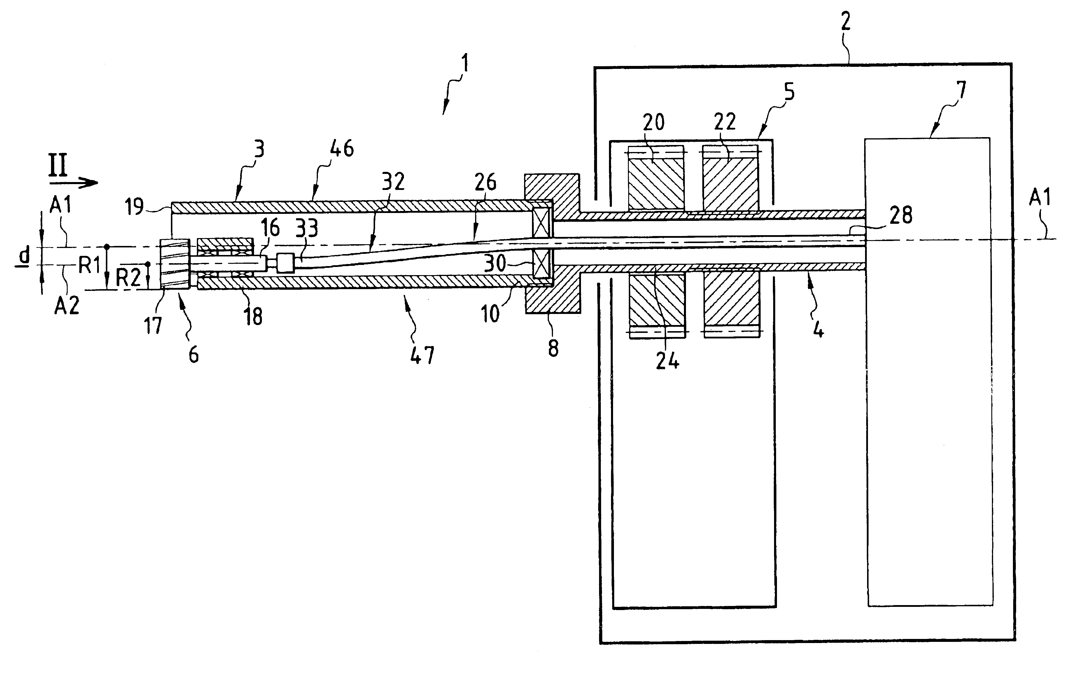
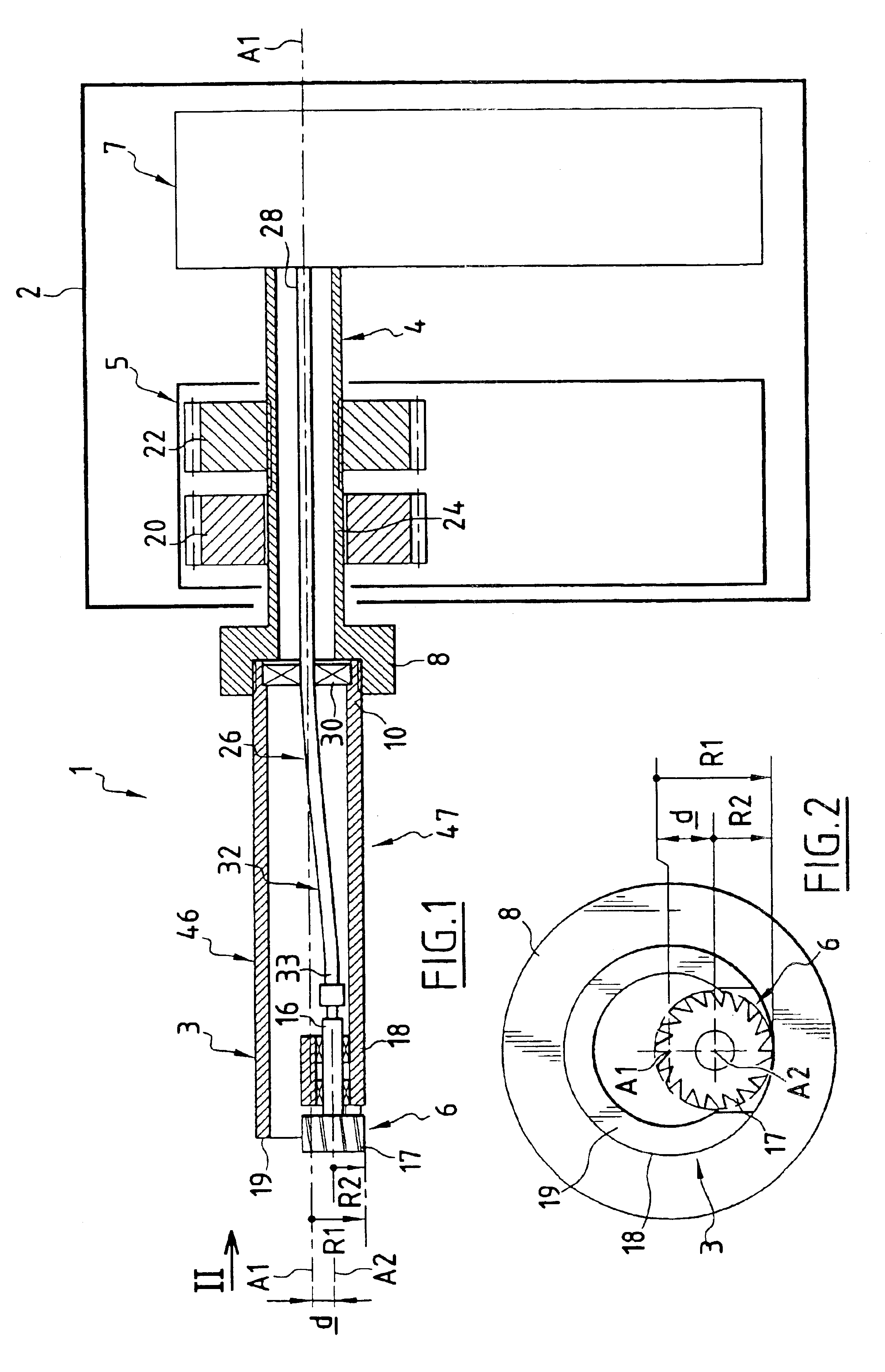
FIG. 1 is a diagram showing a drilling machine 1 for implementing an orbital drilling method.

The machine 1 mainly comprises:

a casing 2;

a cutter support 3 removably mounted on a spindle 4;

means 5 for driving the support 3, these means being housed in the casing 2;

a cutter 6 mounted on the support 3; and

means 7 for driving the cutter 6, these means being housed inside the casing 2.

The support 3 and the spindle 4 extend along a first axis A1 constituting a common central axis. The spindle 4 projects out from the casing 2 via a front or distal end 8, with the remainder of the spindle being received inside the casing 2.

The support 3 has its rear or proximal end 10 mounted at the front or distal end 8 of the spindle 4. The support 3 thus extends the spindle 4 in a forward direction.

By way of example, the support 3 can...


PUM

PropertyMeasurementUnit
radius R1aaaaaaaaaa
axis of rotationaaaaaaaaaa
radiusaaaaaaaaaa

Abstract

The tool comprises firstly a cutter support for being driven in rotation about a first axis of rotation that is to coincide with the axis of the orifice, and a cutter rotatably mounted on the cutter support to rotate about a second axis of rotation parallel to the first axis of rotation and spaced apart therefrom by a non-zero offset distance. A front segment of the cutter support has maximum radial extent relative to the first axis of rotation that is less than or equal to the radius of the orifice to enable the front segment to penetrate into the orifice during drilling. The tool is particularly applicable to drilling machines used in the aviation industry.

Description

The present invention relates to a tool for drilling an orifice, the tool being of the type comprising:a cutter support designed to be rotated about a first axis of rotation that is to coincide with the axis of the orifice; anda cutter rotatably mounted on the cutter support and having a central axis forming a second axis of rotation parallel to the first axis of rotation and spaced apart therefrom by a non-zero offset, the cutter being designed to be rotated about the second axis of rotation relative to the cutter support in order to drill the orifice.The invention applies in particular to drilling tools used in the aviation industry.A tool of the above-specified type makes use of an "orbital" drilling method, where "orbital" refers to the motion of the cutter about the first axis of rotation.Compared with a conventional tool in which the cutting head is a drill bit on the axis of the orifice to be drilled, such an orbital tool makes it possible to reduce both the rotary driving to...

Claims


Application Information

Patent Timeline
Patent Type & Authority Patents(United States)
IPC IPC(8): B23Q11/00B23C7/00B23C3/02B23C3/34B23C3/00
CPCB23C3/02B23C7/00B23Q11/0046B23C2220/52B23C2228/14Y10T409/303808Y10T409/307168Y10T409/307112Y10T409/304424Y10T409/304088
Inventor DEBAT, CLAUDEBURELLER, MICHEL
Owner APEX BRANDS
Why Eureka
Try Eureka