System and method for sensing vibrations in equipment

a technology of vibration sensing and equipment, applied in the field of system and method for sensing vibration in equipment, can solve the problems of lack of detail information, erroneous measurement, indirect measurement techniques that are not intrusive,

Inactive Publication Date: 2021-05-13
FUTURE TECH IN SPORT INC
View PDF21 Cites 5 Cited by
  • Summary
  • Abstract
  • Description
  • Claims
  • Application Information

AI Technical Summary

Benefits of technology

[0008]The invention described here overcomes these deficiencies of the prior art by providing a non-obtrusive, properly connected, easily attached sensor that can measure, record, manipulate, construct and transmit several types of measurements, active and passive, and data including high speed vibration, dynamic strain, static strain, three-axis acceleration, three-axis rate of rotation, temperature, pressure, humidity, location, air-quality, and / or any other type of data that can be measured with sensors that will fit within the specified package of the system. The sensor system can collect and interpret data, correlate data with events, perform machine learning functions and thus provide useful information to the end user.
[0009]It is an object of the invention to provide a sensor package that has a low profile so that movement and acceleration do not cause substantial inertial forces on the adherence method. Furthermore, it is an objective of the invention to describe a sensor package that is hermetically sealed against the environment so that a bulky enclosure that increases stresses on the adherence method is not required. It is also an objective of the invention to describe a sensor package that can conform to the structure of the host device, thereby proving ample surface area for adherence.
[0010]One attribute of the sensor is its form factor. The sensor can be less than 2 mm thick with a density of less than 3.5 kg / m2. This form factor allows it to have several beneficial features. The low area mass density of the system allows it to be soundly adhered to structures and equipment with double sided tape, even in high acceleration environments. The thin nature of the system can negate inertial moments on the adhesive, increasing reliability. Due to the thin nature and physical flexibility of the materials used in its construction, the sensor can conform to common engineering and product shapes and forms. The above features can combine to make the sensor non-obtrusive. The low mass and area mass density of the system severely restricts its influence on the natural frequencies of vibration of the structure it is adhered to, increasing measurement accuracy.
[0011]In an illustrative embodiment, a system for measuring and reporting vibrations can include at least one sensor, at least one transmitting antenna, a central processing unit, a battery, and a package that encapsulates the system, wherein the overall thickness of the package is approximately 2 mm or less. The system can have an inductive wireless charging coil. The system can have at least one sensor that can be a vibration sensor, a dynamic strain sensor, or a vibration and dynamic strain sensor. The vibration and / or dynamic strain sensor can be a piezo ceramic. The vibration and / or dynamic strain sensor can be a piezo polymer. The system can include an inertial sensor. The system can include a static strain sensor. The system can have a mass density of approximately 3.5 kg / m2 or less. The system the system can be adhered to a structure with an adhesive with a peel strength of approximately 550 Pa or more and adhesive strength of approximately 2.2 kPa or more. The adhesive can be a double sided tape. The package can be constructed with flexible polymer materials that allow the system to conform to engineering surfaces. The system can conform to a radius of approximately ¾ or less. The outer encapsulation can allow for the addition of printed logo and branding. The branding or logo can allows for the system under the branding or logo to be hidden from the user. The central processing unit can perform analog-to-digital signal conversion. The processing unit is capable of digital signal filtering. The processing unit is capable of packaging and delivering wireless signals to another device. The processing unit is capable of receiving firmware-over-the-air updates.
[0013]In an illustrative embodiment, a method for measuring and reporting vibrations can include obtaining a bat having a system for measuring and reporting vibrations, the system for measuring and reporting vibrations including at least one sensor, at least one transmitting antenna, a central processing unit, a battery, and a package encapsulating the system, wherein the overall thickness of the package is approximately 2 mm or less, swinging the bat at a ball, impacting the ball with the bat, and causing a signal to be sent from the bat to a receiver indicating that an impact occurred.

Problems solved by technology

Thus, by trying to measure the natural frequencies of the system, the actual frequencies are altered, resulting in erroneous measurements being made.
Indirect measurement techniques are non-intrusive but lack the detail information that can only be gathered by physical contact with the system.
These sensors have been bulky, heavy, of substantial thickness, intrusive, power hungry, and expensive.
This performance increase is driven by the fact that heavier equipment experiences larger forces for the same acceleration, bulky devices tend not to conform to surfaces and thick enclosures increase the inertia of the system, causing edges to experience substantially larger forces and peel during movement and accelerations.
These factors combine to place significant stress on the adherence mechanism employed to attach the sensor system to the host, often requiring intrusive methods such as one or more screws, hard-and / or slow-curing epoxies and snap on systems that have to be designed into the host system.
Furthermore, attaching these sensors to the plant, equipment, machinery or infrastructure involves labor intensive and intrusive practices in order to ensure proper measurement and robustness and requires substantial human intervention.
Intrusive attachment of third party devices can potentially negate the original equipment manufacturer's warranty of said equipment.

Method used


Image

  • System and method for sensing vibrations in equipment
  • System and method for sensing vibrations in equipment
  • System and method for sensing vibrations in equipment

Examples


Embodiment Construction

[0019]The invention described here combines multiple sensors in a small, unobtrusive and slight form factor package that is easily and non-intrusively applied to functional structures in order to sense, record, capture and transmit information of said structures to edge devices, control systems, databases, machine learning algorithms and other processes and functions that can benefit from said information.

[0020]Objects of the invention include is its multi-functionality, its low profile and its ease of application and use. These factors combine to create a novel, rapidly deployable, ubiquitous sensor system and / or network that has utility in the fields of sports, medicine, defense, oil-and-gas, aerospace, automotive, industrial processes, maintenance, health-monitoring, controls and many more.

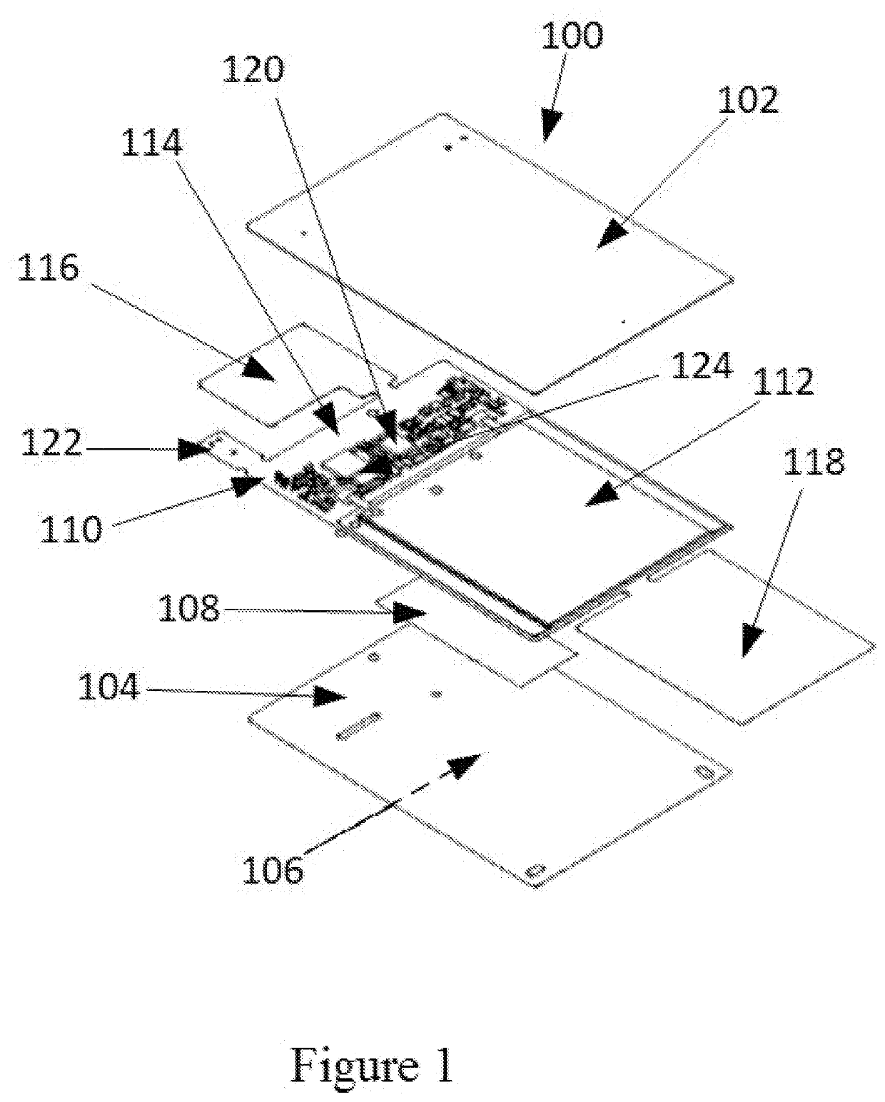
[0021]FIG. 1 is an exploded view of the sensor, according to an illustrative embodiment. The sensor system 100 can be entirely encapsulated between top layer 102 and bottom layer 104. Top layer...


PUM


Abstract

This invention provides a low-profile, highly-sensitive, high-frequency sensor that can be affixed to equipment. Low-profile electronics with the ability to capture and analyze specific signals of concern can be utilized as to remain unobtrusive. Vibration data can be captured and stored locally on the equipment where user-defined code can analyze data and pick specific parameters of concern to send via the wireless communications link to a receiver. The receiver is able to capture the data and monitor parameters of the equipment.

Description

FIELD OF THE INVENTION[0001]This invention relates to manufacturing and applying high-frequency vibration sensors to industrial equipment, electronics to interpret vibrations, software to identify information regarding vibration and methods to communicate vibration related information to devices physically removed from the equipment.BACKGROUND OF THE INVENTION[0002]The Internet-of-Things (IoT) age of micro-electronic devices, connected servers, large-cloud-based storage and fast acting machine learning algorithms rely on large arrays of distributed sensors. In the fields of structural health monitoring and predictive maintenance there is a need for great number of sensors to be distributed over all areas of the plant often in remote or hard to reach areas in order to continuously and in real-time monitor the health of machinery, equipment and other infrastructure.[0003]The field of structural health monitoring is well-established with many products and solutions being offered to con...

Claims


Application Information

Patent Timeline
Patent Type & Authority Applications(United States)
IPC IPC(8): G01H11/08G01P15/09
CPCG01H11/08G01P15/09A63B2220/80A63B2220/53A63B2220/64A63B2225/50A63B2225/20A63B2102/18A63B2220/833A63B60/46G01L5/0052A63B2220/10A63B2220/30A63B2220/40A63B2220/20
Inventor PRETORIUS, JACOB VAN REENENFRY, JAMESBODNAR, ERIC OLEG
Owner FUTURE TECH IN SPORT INC
Why Eureka
Try Eureka