
Electromechanical pressure sensor

a technology of electromechanical and pressure sensor, applied in the direction of vacuum gauges, measuring devices, instruments, etc., can solve the problem that the resonance structure cannot be miniaturized up to a certain level

Active Publication Date: 2021-05-13
KING ABDULLAH UNIV OF SCI & TECH
View PDF0 Cites 1 Cited by
  • Summary
  • Abstract
  • Description
  • Claims
  • Application Information

AI Technical Summary

Benefits of technology

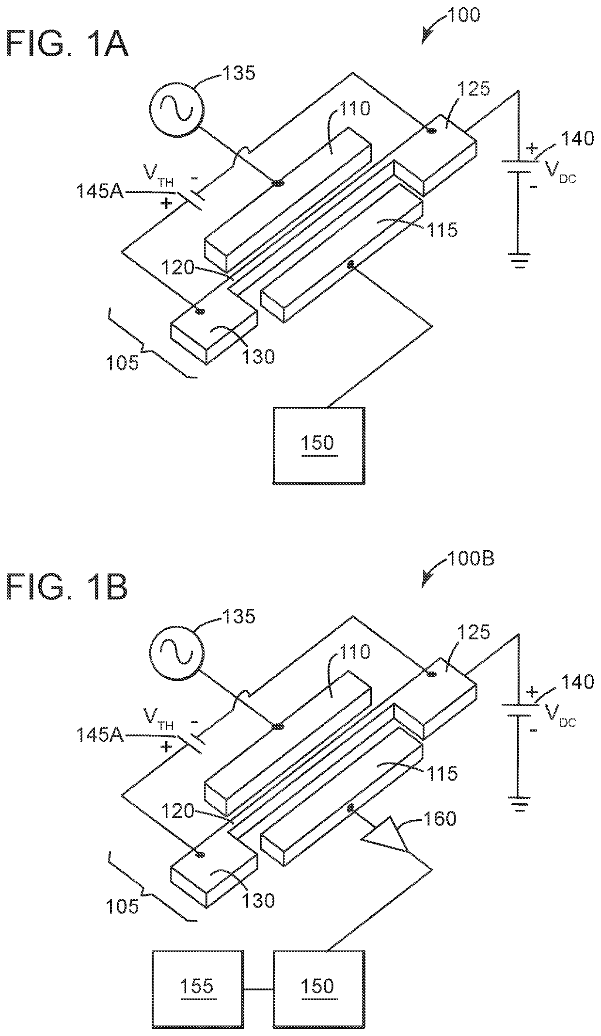
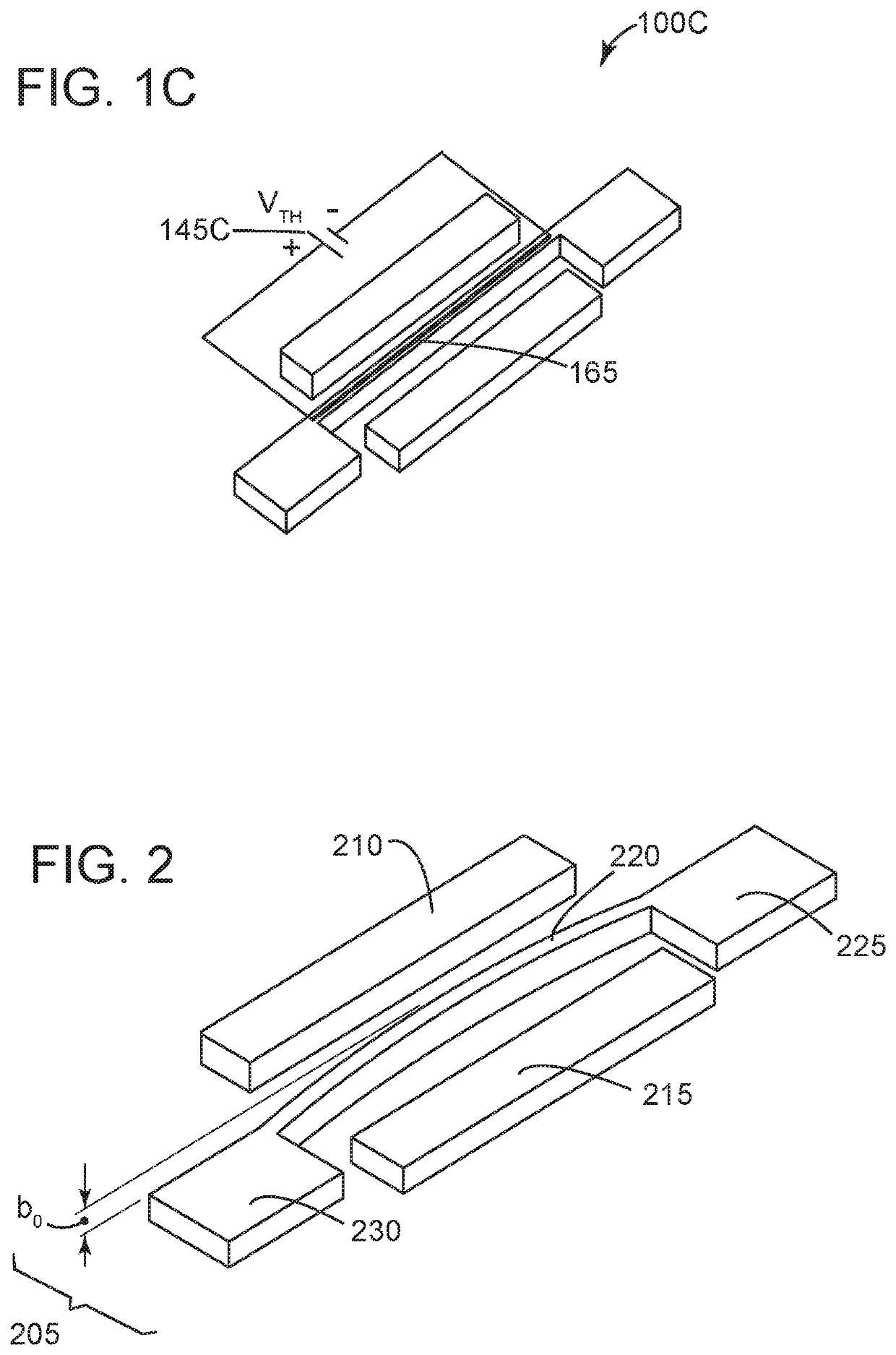
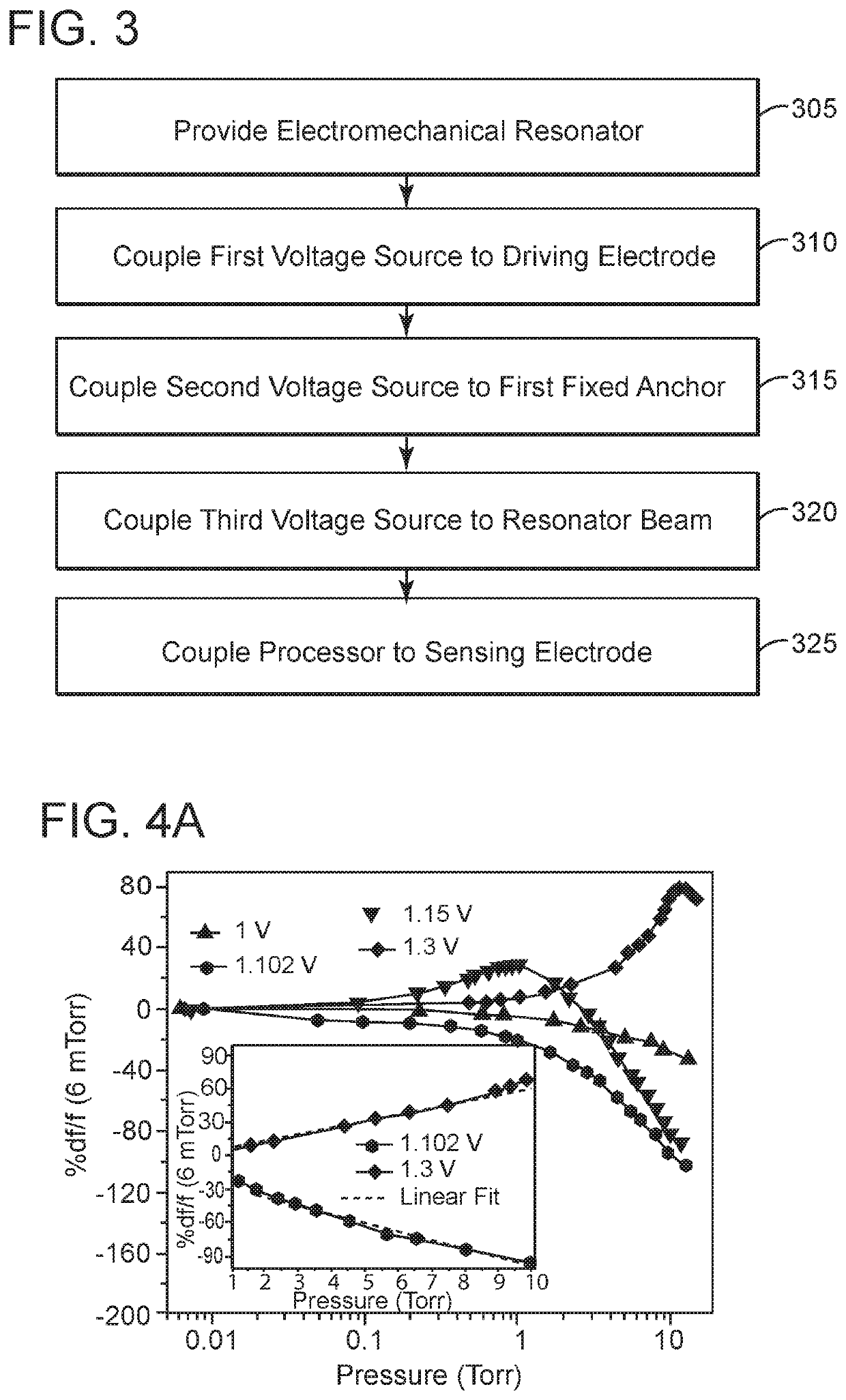
This patent describes an electromechanical pressure sensor that uses an electromechanical resonator to measure pressure. The sensor includes a beam resonator with a driving electrode, a sensing electrode, and a resonator beam that is coupled between the driving and sensing electrodes. The resonator beam is heated using a current from a DC bias voltage source. A temperature difference is created between the resonator beam and the fixed anchors, and the resulting temperature change is measured using a third voltage source. This change in temperature is correlated with the pressure value to determine the pressure. The sensor has improved accuracy and sensitivity to pressure compared to other sensors. The method of producing the sensor involves creating the resonator beam, applying an alternating current to it, and measuring the resulting temperature change. The invention is useful for a variety of applications where precise pressure measurements are needed.

Problems solved by technology

Moreover, the resonant structure can only be miniaturized up to a certain level depending on the spot-size of the laser source used for the local heating of the beam.

Method used


Image

  • Electromechanical pressure sensor
  • Electromechanical pressure sensor
  • Electromechanical pressure sensor

Examples


Embodiment Construction

[0018]The following description of the exemplary embodiments refers to the accompanying drawings. The same reference numbers in different drawings identify the same or similar elements. The following detailed description does not limit the invention. Instead, the scope of the invention is defined by the appended claims. The following embodiments are discussed, for simplicity, with regard to the terminology and electromechanical resonators.

[0019]Reference throughout the specification to “one embodiment” or “an embodiment” means that a particular feature, structure or characteristic described in connection with an embodiment is included in at least one embodiment of the subject matter disclosed. Thus, the appearance of the phrases “in one embodiment” or “in an embodiment” in various places throughout the specification is not necessarily referring to the same embodiment. Further, the particular features, structures or characteristics may be combined in any suitable manner in one or mor...


PUM

PropertyMeasurementUnit
widthaaaaaaaaaa
widthaaaaaaaaaa
thicknessaaaaaaaaaa

Abstract

An electromechanical pressure sensor includes an electromechanical resonator having a driving electrode, a sensing electrode, and a beam resonator arranged between the driving and sensing electrodes. The beam resonator includes a resonator beam coupled on a first end to a first fixed anchor and coupled on a second end to a fixed second fixed anchor. The electromechanical resonator also includes a first voltage source coupled to the driving electrode and configured to provide an alternating current to the driving electrode and a second voltage source coupled to the first fixed anchor. The second voltage source provides a DC bias to the resonator beam. The electromechanical resonator further includes a third voltage source coupled to the resonator beam via the first and second fixed anchors. The third voltage source is configured to supply a voltage to the resonator beam that results in a temperature differential between the resonator beam and the first and second fixed anchors. The electromechanical resonator also includes a processor coupled to the sensing electrode and configured to correlate a voltage on the sensing electrode with a pressure value.

Description

CROSS-REFERENCE TO RELATED APPLICATIONS[0001]This application claims priority to U.S. Provisional Patent Application No. 62 / 536,074, filed on Jul. 24, 2017, entitled “Scalable Pressor Sensor Based on Electrothermally Operated Resonator,” and to U.S. Provisional Patent Application No. 62 / 677,418, filed on May 29, 2018, entitled “Electromechanical Pressure Sensor,” the disclosures of which are incorporated here by reference in their entirety.BACKGROUNDTechnical Field[0002]Embodiments of the disclosed subject matter generally relate to an electromechanically pressure sensor having a resonator with a beam that is electrothermally heated.Discussion of the Background[0003]Pressure sensors are used to provide accurate estimation of the surrounding pressure in a variety of applications. Conventional pressures sensors, which are relatively bulky, include strain-gauge, capacitive, bridge resistors, and piezo-resistive pressure sensors.[0004]There has been recent interest in alternative approa...

Claims


Application Information

Patent Timeline
Patent Type & Authority Applications(United States)
IPC IPC(8): G01L9/00
CPCG01L9/001G01L9/0013G01L9/0019G01L21/22G01L19/0069
Inventor HAJJAJ, AMALHAFIZ, MD ABDULLAH ALYOUNIS, MOHAMMAD IBRAHIM
Owner KING ABDULLAH UNIV OF SCI & TECH
Learn More