
Stereolithography apparatus

a stereolithography and apparatus technology, applied in the field of stereolithographic 3d printing, can solve the problems of reducing the energy efficiency of stereolithography apparatuses containing such elements, reducing the total power of optical radiation transmitted through the photomask, and affecting the heating of the photomask and/or the resin

Pending Publication Date: 2021-05-20
PLANMECA
View PDF8 Cites 5 Cited by
  • Summary
  • Abstract
  • Description
  • Claims
  • Application Information

AI Technical Summary

Benefits of technology

The invention is a stereolithography apparatus that uses a radiative element, a masking element, and an intensity-unifying arrangement to create precise patterns. The apparatus has a linear segment between the radiative element and the masking area, and the intensity-unifying arrangement has reflective surfaces that collect optical radiation from the radiative element and partially mask it onto the masking area. The reflective surfaces have non-decreasing distances from the linear segment and follow a boundary of a rectangle. The invention allows for improved accuracy and precision in creating patterns.

Problems solved by technology

However, provision of intensity-unifying elements may induce noticeable optical losses, decreasing total power of optical radiation transmitted through the photomask and reducing energy efficiency of stereolithography apparatuses comprising such elements.
This may lead to issues related to the heating up of the photomask and / or the resin.

Method used


Image

  • Stereolithography apparatus
  • Stereolithography apparatus
  • Stereolithography apparatus

Examples


Embodiment Construction

[0029]Concerning the stereolithography apparatuses discussed in this detailed description, the following shall be noted.

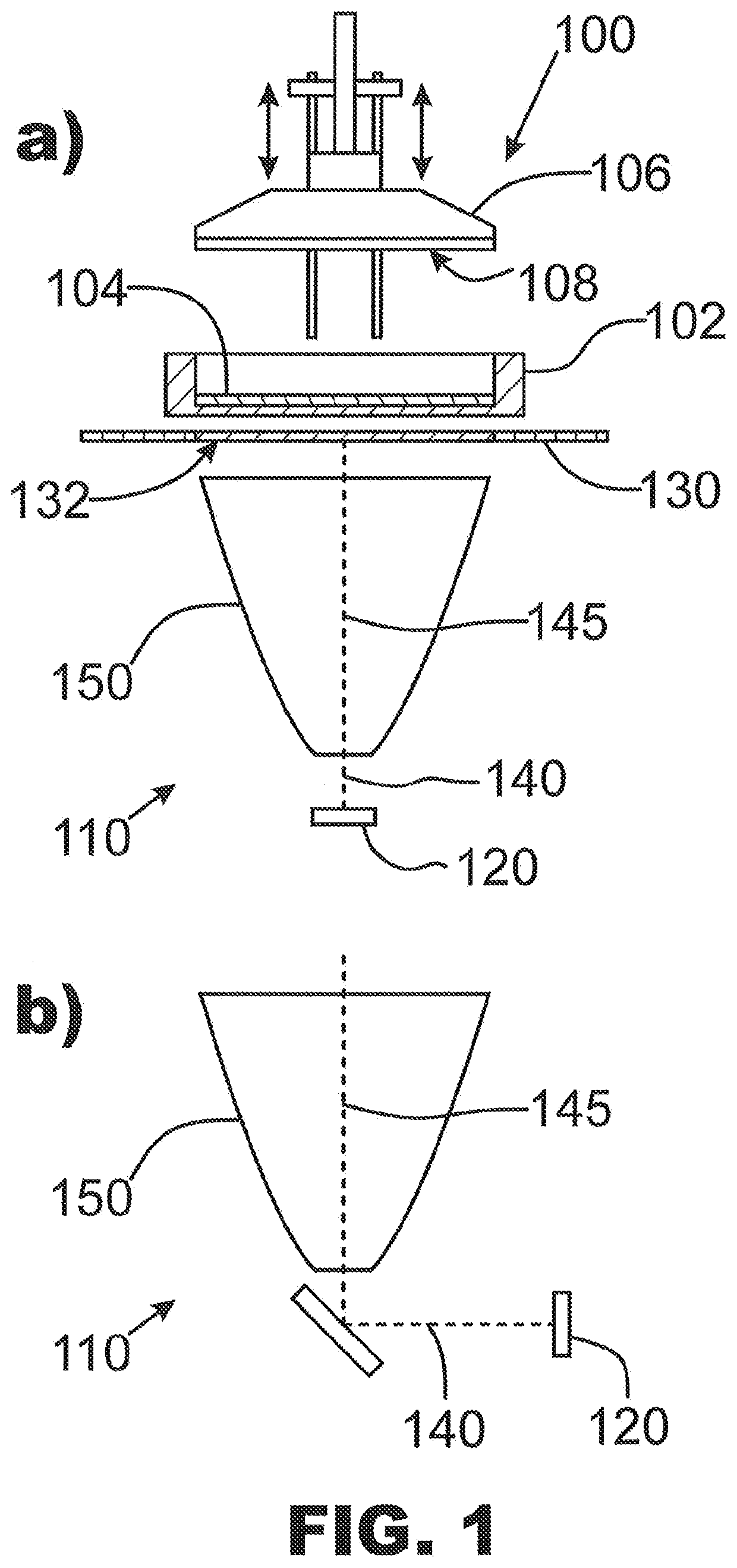
[0030]A stereolithography apparatus can also be called a stereolithographic 3D printer, or a stereolithographic additive manufacturing apparatus. A stereolithography apparatus may be a 3D printer for fabrication of dental objects. It may be a 3D printer for creating dental splints, models, surgical guides, temporary fillings, and orthodontic models with true precision and efficiency. Additionally or alternatively, a stereolithography apparatus may be a 3D printer for fabrication of any stereolithographically 3D-printable objects other than dental objects.

[0031]Further, a stereolithography apparatus may comprise any of a controller, a reader(s) and / or sensor(s) block, a data interface, a user interface, a power block, a base part, a lid, a lid mechanism, a vat, a build platform, a build platform mechanism, a resin delivery mechanism, a resin heater part, an exposure...


PUM

PropertyMeasurementUnit
sizeaaaaaaaaaa
sizeaaaaaaaaaa
lengthaaaaaaaaaa

Abstract

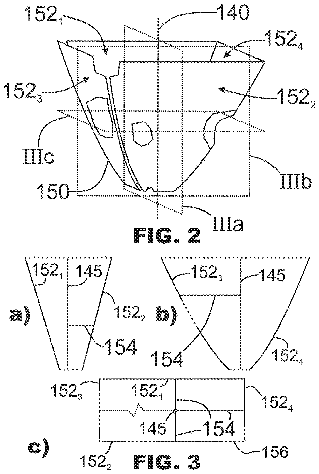
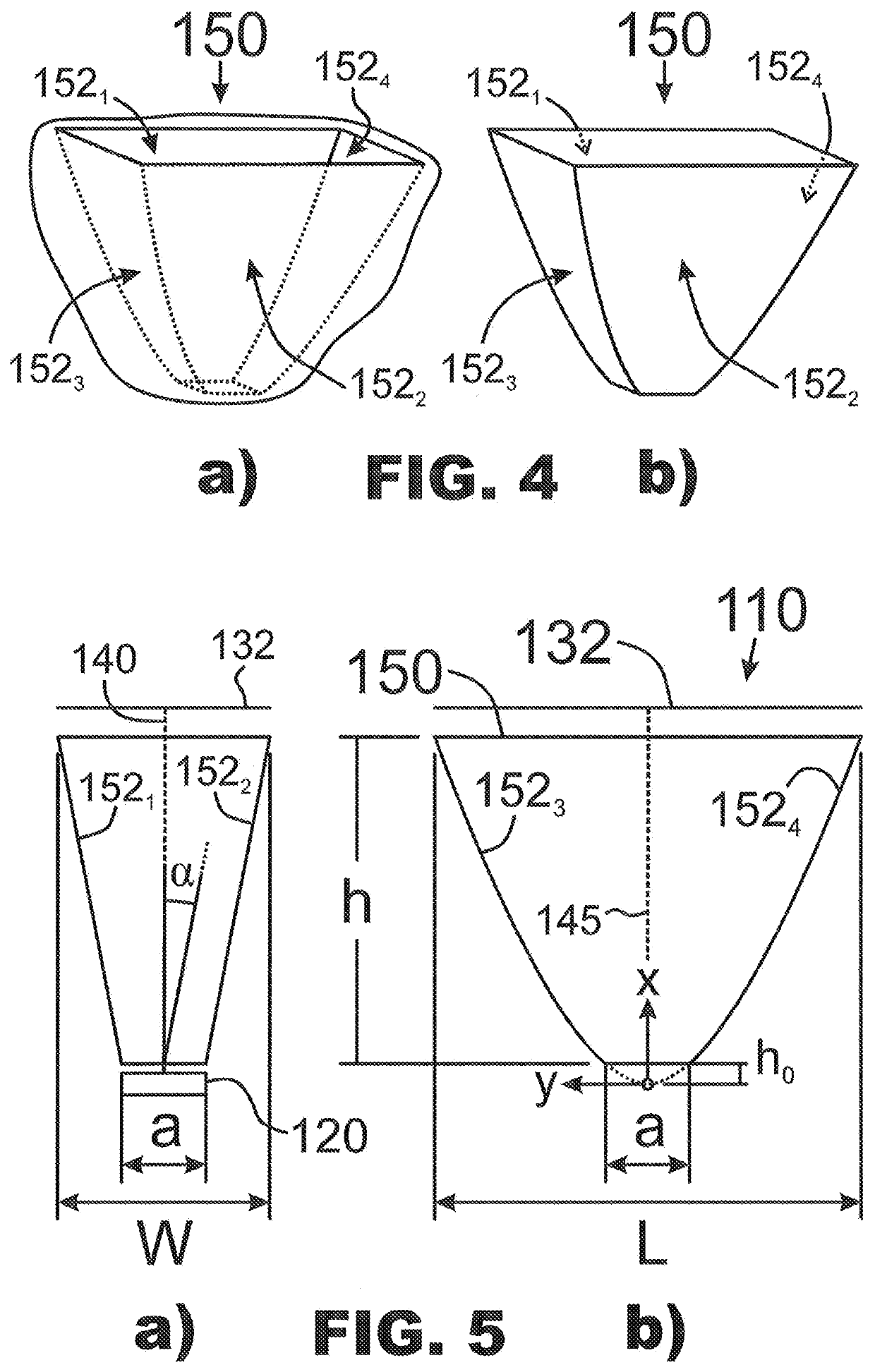
A stereolithography apparatus (100) has an exposure arrangement (110), comprising a radiative element (120); a masking element (130), having a substantially rectangular masking area (132); an optical path (140) between the radiative element (120) and the masking area (132), having a linear segment (145); and an intensity-unifying arrangement (150), having a first, a second, a third, and a fourth reflective surface (1521, 1522, 1523, 1524) The first and second reflective surfaces (1521, 1522,) are arranged on opposite sides of the linear segment (145), and the third and fourth reflective surfaces (1523, 1524) are arranged on opposite sides of the linear segment (145). In a cross section of the intensity-unifying arrangement (150) along any plane, perpendicularly intersecting the linear segment (145), the reflective surfaces (1521, 1522, 1523, 1524) follow a boundary (156) of a rectangle.

Description

FIELD OF THE INVENTION[0001]The invention concerns the technology of stereolithographic 3D printing, also known as stereolithographic additive manufacturing. In particular, the invention concerns stereolithography apparatuses with photomask-based exposure arrangements.BACKGROUND OF THE INVENTION[0002]Stereolithography is a 3D printing or additive manufacturing technique in which optical radiation is used to photopolymerize suitable raw material to produce the desired object. The raw material comes to the process in the form of a resin. A vat is used to hold an amount of resin, and a build platform is moved in the vertical direction so that the object to be produced grows layer by layer onto a build surface of the build platform. The optical radiation used for photopolymerizing may come from above the vat, in which case the build platform moves downwards through the remaining resin as the manufacturing proceeds. The present description concerns in particular the so-called “bottom up”...

Claims


Application Information

Patent Timeline
Patent Type & Authority Applications(United States)
IPC IPC(8): B29C64/291B33Y30/00B29C64/129B29C64/286
CPCB29C64/291B29C64/286B29C64/129B33Y30/00B33Y10/00B29C64/264G02B27/0994G02B19/0023G02B19/0061B29C64/00
Inventor RAKKOLAINEN, TEROKOIVISTO, JUHA
Owner PLANMECA
Learn More