
Turbine ring assembly with inter-sector sealing

a technology of inter-sector ring and ring assembly, which is applied in the direction of engine fuction, machine/engine, leakage prevention, etc., can solve the problems of limited temperature level to which the cmc ring can be subjected, and the sealing between the gas flowpath on the internal the external side of the ring sector remains a problem, so as to reduce production costs and prevent leakage , the effect of simplifying the mounting of the inter-

Active Publication Date: 2021-06-03
SN DETUDE & DE CONSTR DE MOTEURS DAVIATION S N E C M A
View PDF0 Cites 0 Cited by
  • Summary
  • Abstract
  • Description
  • Claims
  • Application Information

AI Technical Summary

Benefits of technology

The invention is about a cooling system for a gas turbine engine. The system uses elbow sealing elements to prevent leaks at the contact points between sealing tabs, which can occur at the junctions between grooves. The elbow sealing elements are not necessary when using sealing tabs that have two continuous portions forming an angle between them. The use of these sealing tabs simplifies the mounting and production process of the cooling system and reduces the risk of reintroducing hot air into the flowpath. This invention also provides better protection for the faces of adjacent ring sectors and sealing tabs from high temperature streams.

Problems solved by technology

However, the sealing between the gas flowpath on the internal side of the ring sectors and the external side of the ring sectors remains a problem.
Therefore, the temperature level to which the CMC rings can be subjected is limited by the presence of the sealing tabs.

Method used


Image

  • Turbine ring assembly with inter-sector sealing
  • Turbine ring assembly with inter-sector sealing
  • Turbine ring assembly with inter-sector sealing

Examples


Embodiment Construction

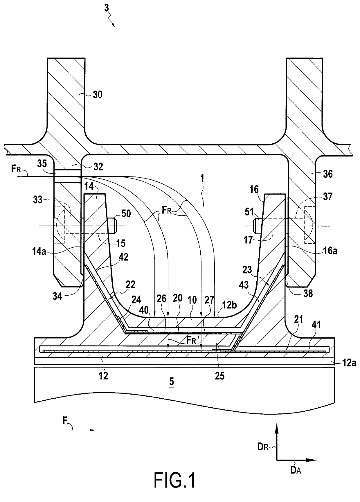
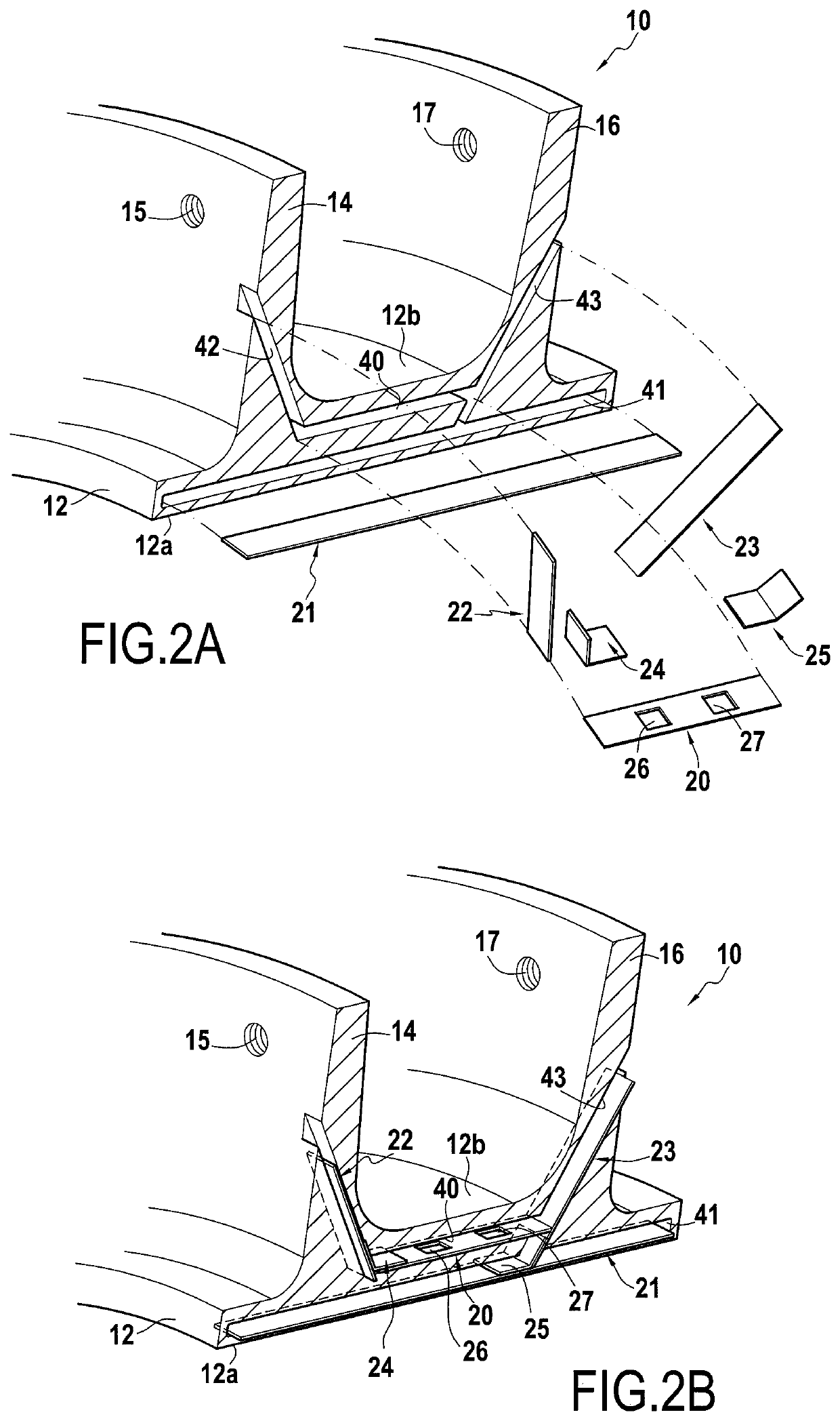
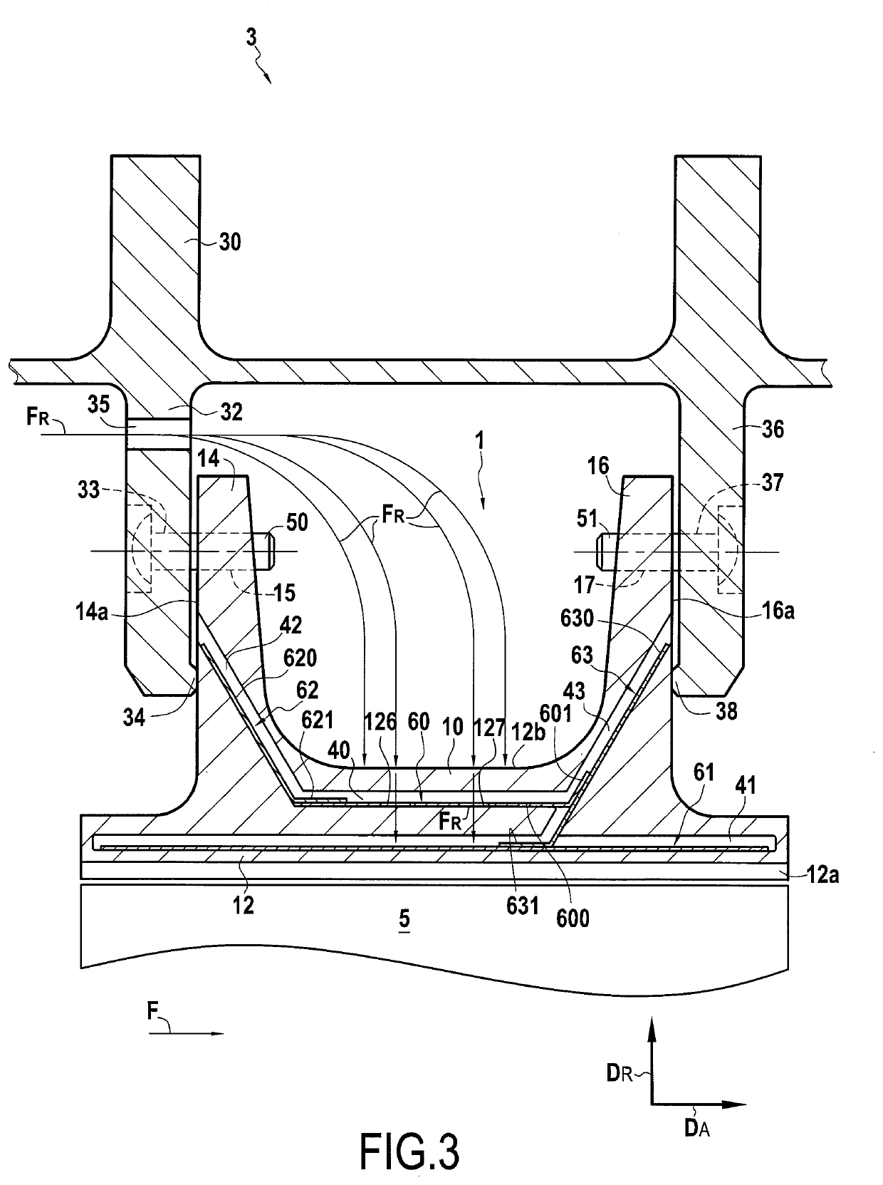
[0031]FIG. 1 shows a high-pressure turbine ring assembly comprising a turbine ring 1, here made of ceramic-matrix composite (CMC) material comprising a plurality of adjacent ring sectors each having an annular base or platform 12, an upstream lug 14 and a downstream lug 16 protruding each radially outwardly from the platform 12. In the example described here, the turbine ring 1 surrounds a set of rotary airfoils 5. However, the ring assembly of the invention can also be formed by other turbine ring assemblies such as for example a turbine ring assembly comprising gas turbine diffuser sector vanes. In this case, the platform is a platform of a diffuser and the upstream and downstream lugs 14, 16 can carry sealing means and / or fixing means in order to come into sealed contact with the casing. In each case, the turbine ring 1 is formed of a plurality of adjacent ring sectors 10, FIG. 1 being a radial sectional view along a plane passing between two contiguous ring sectors. The arrow DA...


PUM


Abstract

A turbine ring assembly includes adjacent ring sectors forming a turbine ring, each ring sector having a platform with an inner face defining the inner face of the turbine ring and an outer face from which an upstream lug and a downstream lug extend along the radial direction. Each ring sector includes a first groove present in the platform in the vicinity of the inner face of the platform, a second groove present in the platform in the vicinity of the outer face of the platform, an upstream groove extending into the upstream lug and a downstream groove extending into the downstream lug. A first sealing tab extends into the first groove. A second sealing tab extends into the second groove. An upstream sealing tab extends into the upstream groove. A downstream sealing tab extends into the downstream groove. The second sealing tab includes at least one opening.

Description

BACKGROUND OF THE INVENTION[0001]The invention relates to a turbine ring assembly for a turbomachine, which assembly comprises a plurality of one-piece ring sectors made of ceramic-matrix composite material or of metal material and a ring support structure.[0002]The field of application of the invention is in particular that of gas turbine aeronautical engines. The invention is however applicable to other turbomachines, for example industrial turbines.[0003]The ceramic-matrix composite or CMC materials are known for their good mechanical properties which make them suitable for constituting structural elements, and for their ability to maintain these properties at high temperatures. The use of CMC for various hot parts of aeronautical engines has already been considered, especially as CMC have a density lower than that of traditionally used refractory metals.[0004]Thus, the production of a turbine ring assembly from CMC ring sectors is in particular described in document WO 2017 / 0606...

Claims


Application Information

Patent Timeline
Patent Type & Authority Applications(United States)
IPC IPC(8): F01D25/24F01D11/08
CPCF01D25/246F01D25/12F01D11/08F01D11/005F05D2220/323F05D2240/11F05D2260/201F05D2300/6033F05D2230/60F05D2240/55
Inventor JARROSSAY, CLÉMENTCONGRATEL, SÉBASTIEN SERGE FRANCISDANIS, ANTOINE CLAUDE MICHEL ETIENNEDUFFAU, CLÉMENT JEAN PIERREQUENNEHEN, LUCIEN HENRI JACQUES
Owner SN DETUDE & DE CONSTR DE MOTEURS DAVIATION S N E C M A
Learn More