Power supply device

a power supply device and power supply technology, applied in power supply testing, visible signalling systems, transmission systems, etc., can solve the problems of unstable voltage vo, difficult connection of oscilloscopes or the like, and change in the environment in which noise is transmitted, and achieve the effect of clear identification

Active Publication Date: 2021-06-03
COSEL
View PDF0 Cites 0 Cited by
  • Summary
  • Abstract
  • Description
  • Claims
  • Application Information

AI Technical Summary

Benefits of technology

[0009]The invention, having been contrived in consideration of the heretofore described background art, has an object of providing a power supply device such that when an output voltage becomes abnormal, a system manager or the like can easily acquire information effective in identifying a cause of the abnormality.
[0012]Furthermore, a configuration can be such that the power supply device includes a second light emitting element that is installed to be visually recognizable from the exterior, and is driven by the light emitting element control unit, and the light emitting element control unit causes the second light emitting element to be statically illuminated when the output voltage is normal. Alternatively, a configuration can be such that the power supply device includes a second light emitting element that is installed to be visually recognizable from the exterior, and is driven by the light emitting element control unit, and when the output voltage is normal, the light emitting element control unit converts power supply operation information relating to an operation in a device interior into an optical digital signal of a frequency recognized to be statically illuminated when seen by a person, and causes the optical digital signal to be output from the second light emitting element.
[0017]The power supply device of the invention is such that when the output voltage is abnormal, a system manager or the like can easily acquire specific power supply operation information or cause information for identifying a circumstance and a cause of the abnormality. Moreover, when investigating the circumstance and the cause of an output voltage abnormality, a large amount of information can be acquired, with an optical digital signal that can be transmitted wirelessly as a medium, in a state wherein the power supply device is incorporated in a user system, because of which the circumstance and the cause of the Vo abnormality can be efficiently and clearly identified.

Problems solved by technology

For example, a case wherein an excessive load is applied to the power supply device, a protective circuit is activated, and the output voltage Vo decreases, a case wherein a lightning surge penetrates into an input line of the power supply device, an input fuse blows, and the output voltage Vo decreases, a case wherein an unexpectedly large noise current penetrates into the input line or an output line of the power supply device, the power supply device malfunctions, and the output voltage Vo becomes unstable, a case wherein an internal part of the power supply device accidentally fails, and the output voltage Vo decreases, and the like are included, and a wide variety of other cases are also conceivable.
With a view to safety, such as preventing electrocution, however, it is often the case that the power supply device is such that the internal circuit is covered by a housing made of metal or a resin, or installed inside a housing of the user system, because of which connecting an oscilloscope or the like is difficult unless the housing is removed.
Furthermore, there is a possibility of an environment in which noise is transmitted changing when an oscilloscope or the like is connected, because of which, if possible, investigation of the internal circuit is preferably carried out without making contact with the power supply device and the user system.

Method used


Image

  • Power supply device
  • Power supply device
  • Power supply device

Examples


first embodiment

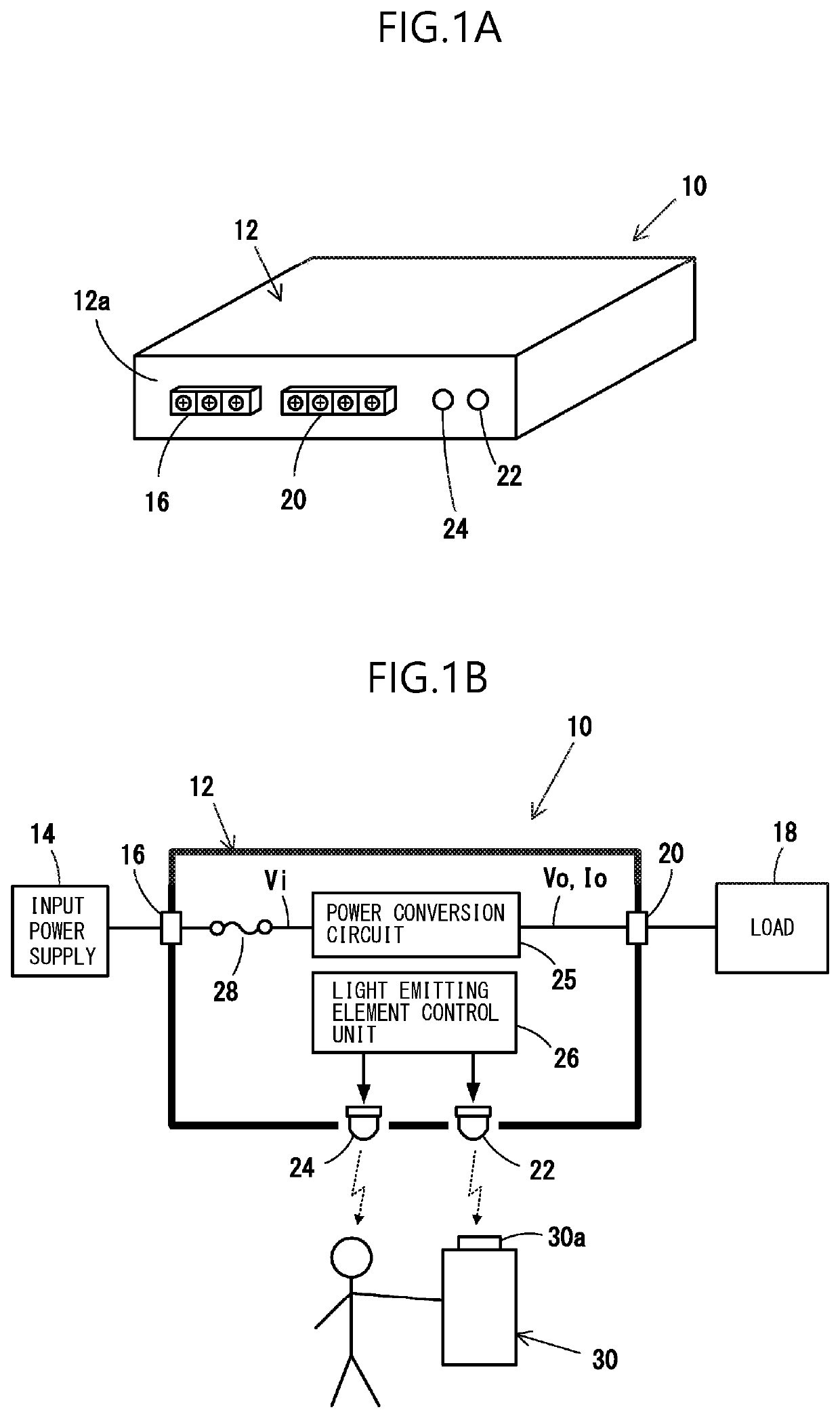
[0029]Hereafter, a power supply device of the invention will be described, based on FIGS. 1A to 6. A power supply device 10 of the embodiment has an approximately cuboid external form, and the six faces are covered by a housing 12, as shown in FIG. 1A. An input side terminal block 16, for wiring the power supply device 10 to an input power supply 14 of a user system, and an output side terminal block 20, for wiring the power supply device 10 to a load 18 of the user system, are provided on a front panel 12a, which is one side face of the housing 12, and first and second light emitting elements 22 and 24 visually recognizable from an exterior are provided.

[0030]As shown in a circuit block diagram of FIG. 1B, the power supply device 10 includes a power conversion circuit 25, which is a switching converter or the like, that converts an input voltage Vi supplied from the input power supply 14 into an output voltage Vo and supplies the output voltage Vo and an output current Io to the lo...


PUM


Abstract

A power supply device is such that when an output voltage is abnormal, a system manager or the like can easily acquire information effective in identifying a cause of the abnormality. The power supply device includes a first light emitting element installed to be visually recognizable from an exterior, and a light emitting element control unit that drives the first light emitting element. When an output voltage is abnormal, the light emitting element control unit causes the first light emitting element to flash, thereby convert at least one of specific power supply operation information used for inferring a cause of the output voltage being abnormal and cause information inferred based on the specific power supply operation information into an optical digital signal formatted for serial communication, and causes the optical digital signal to be output from the first light emitting element. The power supply device includes a second light emitting element that is installed to be visually recognizable from the exterior, and is driven by the light emitting element control unit. When the output voltage is normal, the light emitting element control unit causes the second light emitting element to be statically illuminated.

Description

BACKGROUND OF THE INVENTIONField of the Invention[0001]The present invention relates to a power supply device that converts an input voltage into a predetermined output voltage, and outputs the output voltage.Description of the Background Art[0002]When a user system in which a power supply device is incorporated is operating, and when trouble occurs in the user system due to an abnormality occurring in an output voltage Vo of the power supply system, a system manager has to investigate the cause of the abnormality, and swiftly restore the user system to normal. Because of this, the system manager or a person in charge of maintenance needs to accurately ascertain under what kind of circumstance the power supply device is operating abnormally (the Vo abnormality circumstance), and to identify the cause of this kind of circumstance arising (the cause of the Vo abnormality).[0003]Various cases are conceivable regarding the circumstance and cause of an abnormality of the output voltage V...

Claims


Application Information

Patent Timeline
Patent Type & Authority Applications(United States)
IPC IPC(8): G08B21/18H05B47/105G08B5/36
CPCG08B21/185G08B5/36H05B47/105H02M1/00H02M3/00H02H7/12H02H3/04G08B5/38G08C23/04G01R31/40H05B47/165H02M1/32
Inventor KAWATAKA, NOBUTOHIROSE, YUJIMORIYA, SHINJIHIRAMATSU, MASANOBUKOBAYASHI, HIKARUUSUI, YUTA
Owner COSEL
Why Eureka
Try Eureka