Sacro-iliac joint stabilizing implants and methods of implantation

a technology for stabilizing implants and iliac joints, applied in the field of sacroiliac joint stabilizing implants and methods of implantation, can solve problems such as bone density challenges, and achieve the effect of limiting the amount of implant migration

Pending Publication Date: 2021-06-10
SI BONE
View PDF0 Cites 9 Cited by
  • Summary
  • Abstract
  • Description
  • Claims
  • Application Information

AI Technical Summary

Benefits of technology

[0005]In this aspect, the engaging step may limit the amount of implant mi

Problems solved by technology

Depending on one or more of the delivery trajectory, the target location for implantation, and the configuration of the i

Method used


Image

  • Sacro-iliac joint stabilizing implants and methods of implantation
  • Sacro-iliac joint stabilizing implants and methods of implantation
  • Sacro-iliac joint stabilizing implants and methods of implantation

Examples


Embodiment Construction

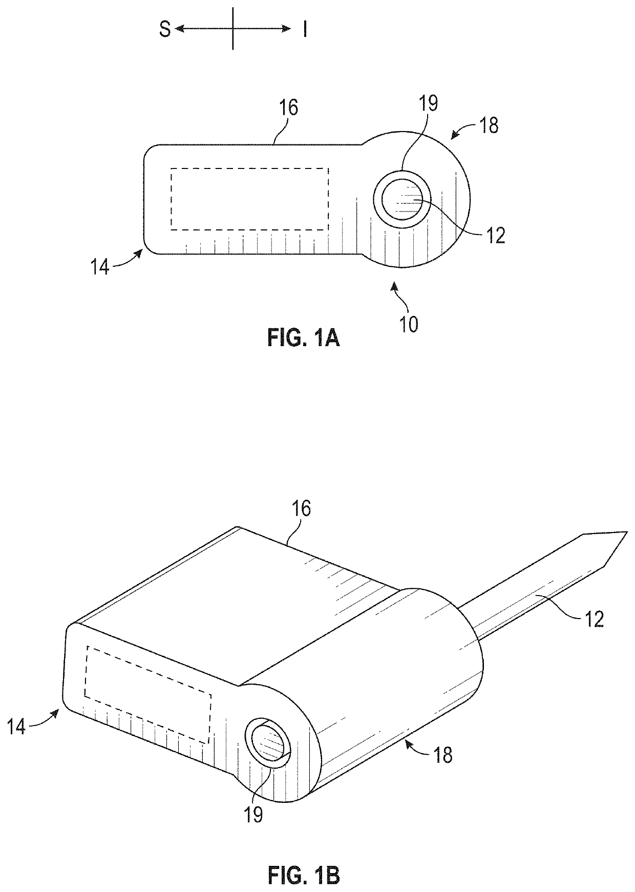
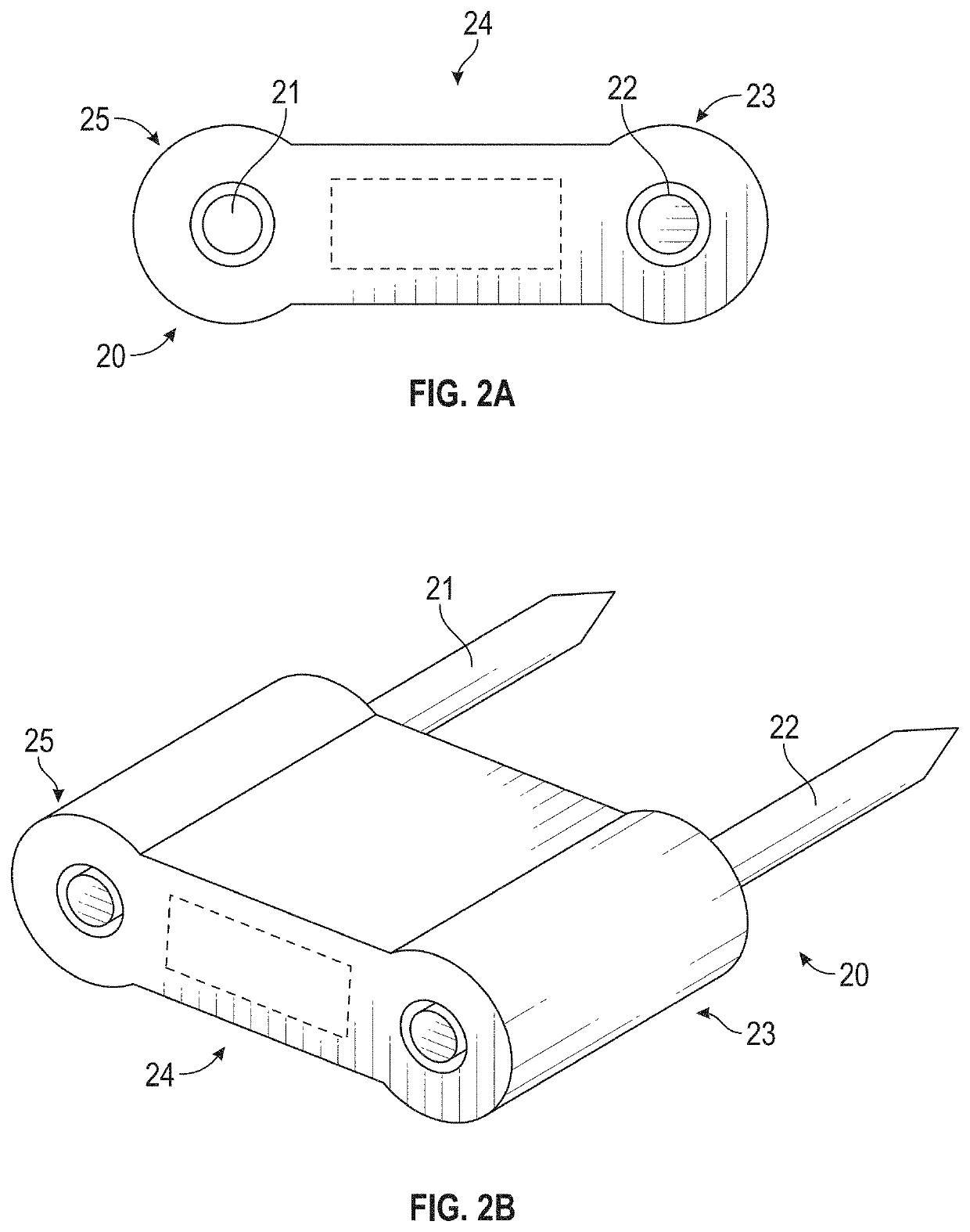
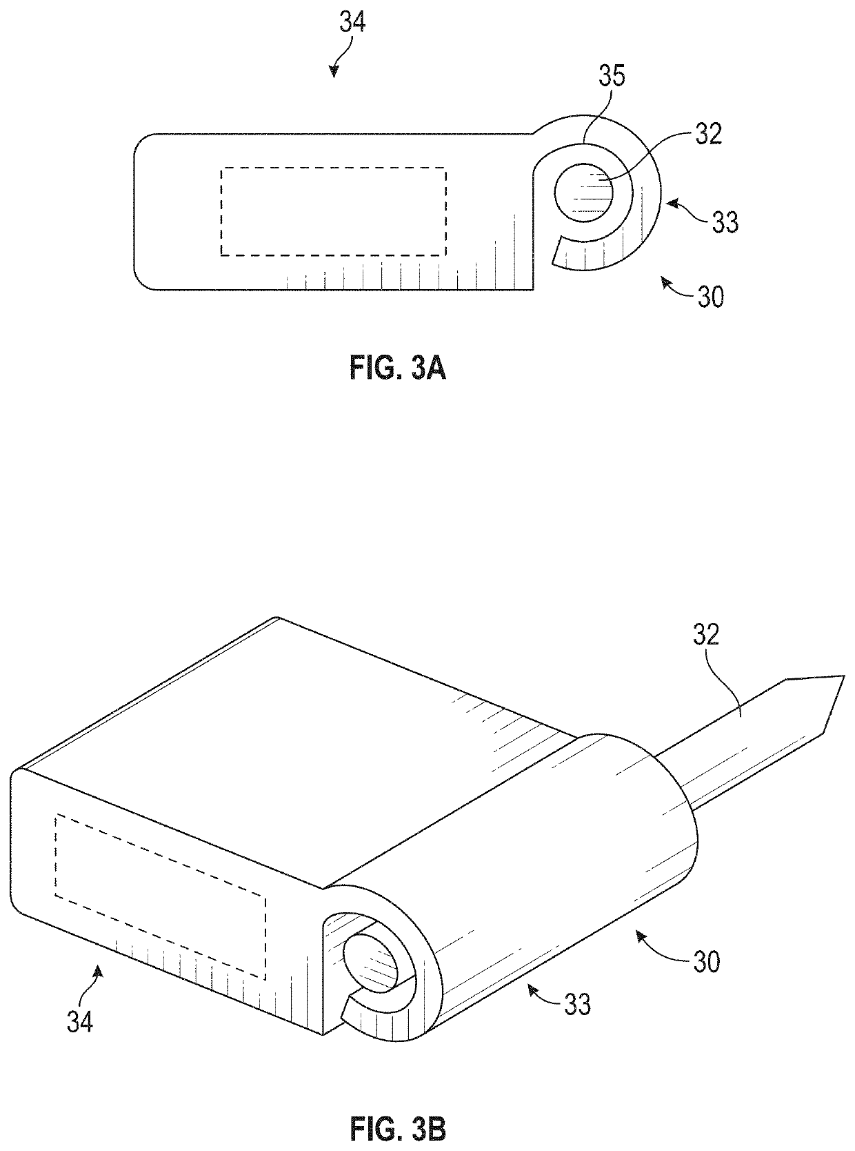
[0025]The disclosure herein is related to SI joint stabilizing implants and methods of implanting SI joint stabilizing implants across a SI joint. The methods include implanting a stabilizing implant from a dorsal approach across the SI joint with a first portion of the implant positioned in the ilium and a second portion of the implant positioned in the sacrum. The implants herein are sized and configured to be implanted according to any of the methods of implantation herein, unless indicated to the contrary.

[0026]Regions of the ilium into which a portion of the implant is positioned may have greater density than regions of the sacrum into which a second portion of the implant is positioned. When positioning a SI joint implant across a SI joint from a dorsal approach, the implant may tend to deflect away from denser cortical iliac bone and migrate towards and into the less dense sacrum, preventing proper positioning of the implant across the SI joint. Implantation methods and impla...


PUM


Abstract

Methods of implanting SI joint stabilization implants across a SI joint from a dorsal approach. The methods may include advancing an elongate implant positioning guide in a dorsal trajectory into an ilium of a subject, directly engaging a guide interface member of a SI joint stabilization implant with the positioning guide to restrict movement of the implant with respect to the positioning guide in at least one direction, and advancing the implant across the SI joint while guiding the implant with the positioning guide.

Description

CROSS REFERENCE TO RELATED APPLICATIONS[0001]This application claims the benefit of priority of U.S. Application No. 62 / 945,653, filed Dec. 9, 2019, the entire disclosure of which is fully incorporated by reference herein for all purposes.INCORPORATION BY REFERENCE[0002]All publications and patent applications mentioned in this specification are herein incorporated by reference to the same extent as if each individual publication or patent application was specifically and individually indicated to be incorporated by reference.BACKGROUND[0003]Implants may be positioned across a sacro-iliac (“SI”) joint to help stabilize the joint. Regions of the ilium may have greater density than regions of the sacrum. Depending on one or more of the delivery trajectory, the target location for implantation, and the configuration of the implant, the differences in bone density may present challenges while advancing some SI joint implants across the SI joint. Implantation methods are needed that acco...

Claims


Application Information

Patent Timeline
IPC IPC(8): A61F2/46A61B17/16A61B17/17
CPCA61F2/4603A61F2002/30995A61B17/1739A61B17/1662A61B17/8897A61B17/1757A61B17/1671A61B17/1659A61B17/68A61F2/30767A61F2002/3013A61F2002/30156A61F2002/30179A61F2002/30772A61F2002/30784A61F2002/30785A61F2002/3093A61F2002/4677A61F2002/4687A61F2/30988A61F2/46A61B2017/564A61B2090/376
Inventor RECKLING, W. CARLTONYERBY, SCOTT A.SAND, PAUL M.
Owner SI BONE
Why Eureka
Try Eureka