Pneumatic tire

Active Publication Date: 2021-06-10
TOYO TIRE & RUBBER CO LTD
View PDF0 Cites 0 Cited by
  • Summary
  • Abstract
  • Description
  • Claims
  • Application Information

AI Technical Summary

Benefits of technology

[0017]By the present configuration, two of the second land portions adjacent to each other in the tire circumferential direction are connected by the connecting portion, so that the second land portion is reinforced and generation of damage such

Problems solved by technology

However, traction performance is not taken into consideration.
In a case where the tire radial dimension of the first land portion is less than 20% of the tire cross-sectional height, the tire radial dimension of the first land portion is small, and it is difficult to obtain the effect of improving the external damage resistance of the sidewall portion by the first land portion.
Accordingly, damage such as cracks is likely to occur in the inner end portion in the tire radial direction of the first land portion, and it is difficult to obtain the effect of improving the external damage resistance of the sidewall portion by the first land portion.
In a case where the ratio is less than 50%, the tire radial dimension of the second land portion is small, and it is difficult to obtain the effect of improving the external damage resistance of the sidewall portion by the second land portion.
In a case where the ratio is larg

Method used


Image

  • Pneumatic tire
  • Pneumatic tire
  • Pneumatic tire

Examples


Embodiment Construction

[0025]Hereinafter, an embodiment of the present invention will be described with reference to the accompanying drawings.

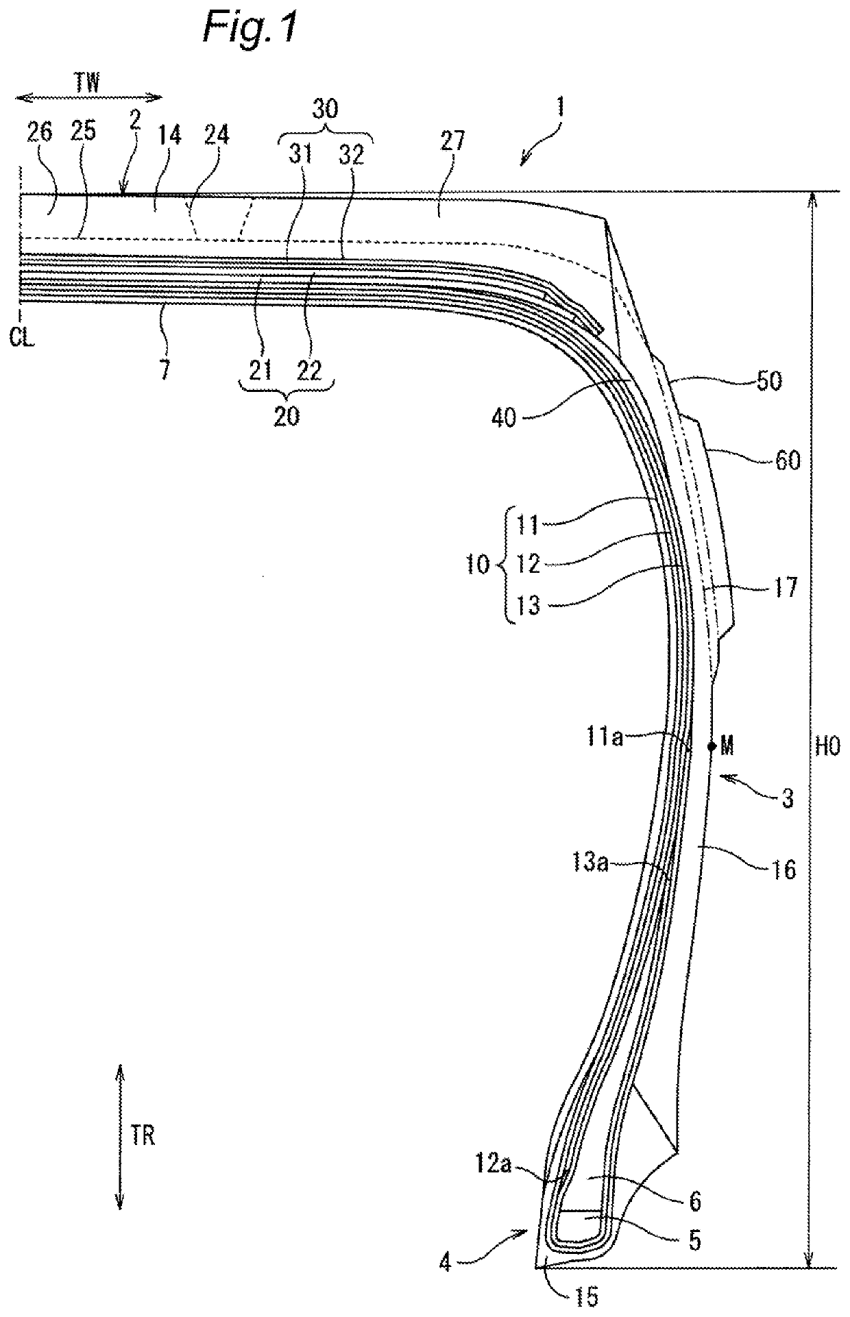
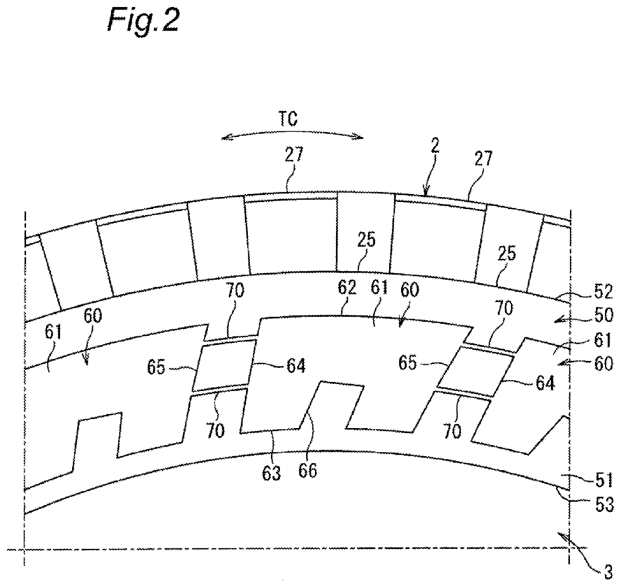
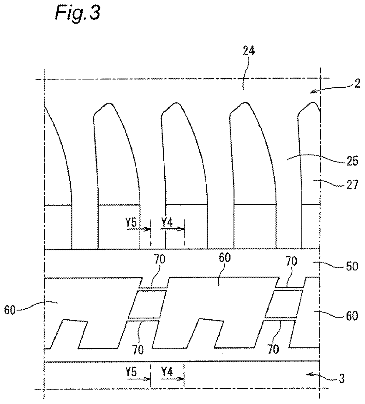
[0026]FIG. 1 is a meridian half cross-sectional view of a pneumatic tire according to the embodiment of the present invention, FIG. 2 is a side view showing part of the pneumatic tire, and FIG. 3 is a development view of main parts of a tread portion and a sidewall portion of the pneumatic tire. A pneumatic tire (hereinafter, also referred to as “tire”) 1 according to the embodiment of the present invention is an off-road tire mounted on a vehicle such as an SUV for traveling on a rough road such as an unpaved road.

[0027]As shown in FIGS. 1 to 3, the pneumatic tire 1 includes a tread portion 2 having a tire tread surface in contact with the road surface, sidewall portions 3 on both sides that extend from the outer side in the tire width direction of the tread portion 2 to the inner side in the tire radial direction and constitute the side surface of the pneumatic t...


PUM


Abstract

A pneumatic tire includes a first land portion that is provided on a sidewall portion, projects to an outer side in a tire width direction, and extends in a tire circumferential direction over the entire tire circumferential direction, and a plurality of second land portions that are provided in a central portion in a tire radial direction of the first land portion, project to an outer side in the tire width direction, extend in the tire circumferential direction, and are disposed apart from each other in the tire circumferential direction.

Description

CROSS-REFERENCE TO RELATED APPLICATIONS[0001]This application claims priority of Japanese Patent Application No. 2019-221430 filed on Dec. 6 2019, the content of which is incorporated herein by reference.BACKGROUND OF THE INVENTIONTechnical Field[0002]The present invention relates to a pneumatic tire.Related Art[0003]A pneumatic tire that includes a protector that projects to the outer side in the tire width direction in a sidewall portion in order to improve the external damage resistance is known. For example, Japanese Patent No. 6446957 discloses a pneumatic tire that includes a protector projecting to the outer side in the tire width direction on a sidewall portion and has a plurality of grooves formed on the protector.SUMMARY[0004]The pneumatic tire disclosed in Japanese Patent No. 6446957 is intended to suppress damage to the protector by providing a plurality of grooves on the protector provided on the sidewall portion. However, traction performance is not taken into consider...

Claims


Application Information

Patent Timeline
IPC IPC(8): B60C13/02
CPCB60C13/02B60C2200/14B60C13/002B60C2013/007
Inventor MATSUBARA, KEISUKE
Owner TOYO TIRE & RUBBER CO LTD
Why Eureka
Try Eureka