Reflective original, exposure method, and device manufacturing method

a technology of exposure method and exposure method, applied in the direction of microlithography exposure apparatus, photomechanical treatment, instruments, etc., can solve the problems of reducing the manufacturing yield of semiconductor devices, unable to meet the requirements of euv light, and the pellicle cannot be configured at a satisfactory strength, so as to reduce the generation of damage

Active Publication Date: 2015-12-15
CANON KK
View PDF8 Cites 0 Cited by
  • Summary
  • Abstract
  • Description
  • Claims
  • Application Information

AI Technical Summary

Benefits of technology

[0015]The present invention provides a reflective original in which generation of damage is reduced even upon application of a thermal load.

Problems solved by technology

This decreases the semiconductor device manufacturing yield.
However, in an EUV exposure apparatus to which the present invention is applied, there is no practical pellicle for EUV light.
However, with this pellicle thickness, the pellicle cannot be configured at a satisfactory strength in both the mechanical aspect upon a change between the atmospheric pressure and the ambient pressure in a vacuum environment when a mask is transferred, and the thermal aspect when EUV light is absorbed and the temperature rises.
Hence, no device can be manufactured.
Thus, the management of a particle on an EUV mask is a critical issue.
On the surface immediately below a laser condensing unit, thermal damage may be generated by high energy of the pulse laser.
Similarly, thermal damage may occur even during particle inspection of an EUV mask.

Method used


Image

  • Reflective original, exposure method, and device manufacturing method
  • Reflective original, exposure method, and device manufacturing method
  • Reflective original, exposure method, and device manufacturing method

Examples


Embodiment Construction

[0031][EUV Exposure Apparatus]

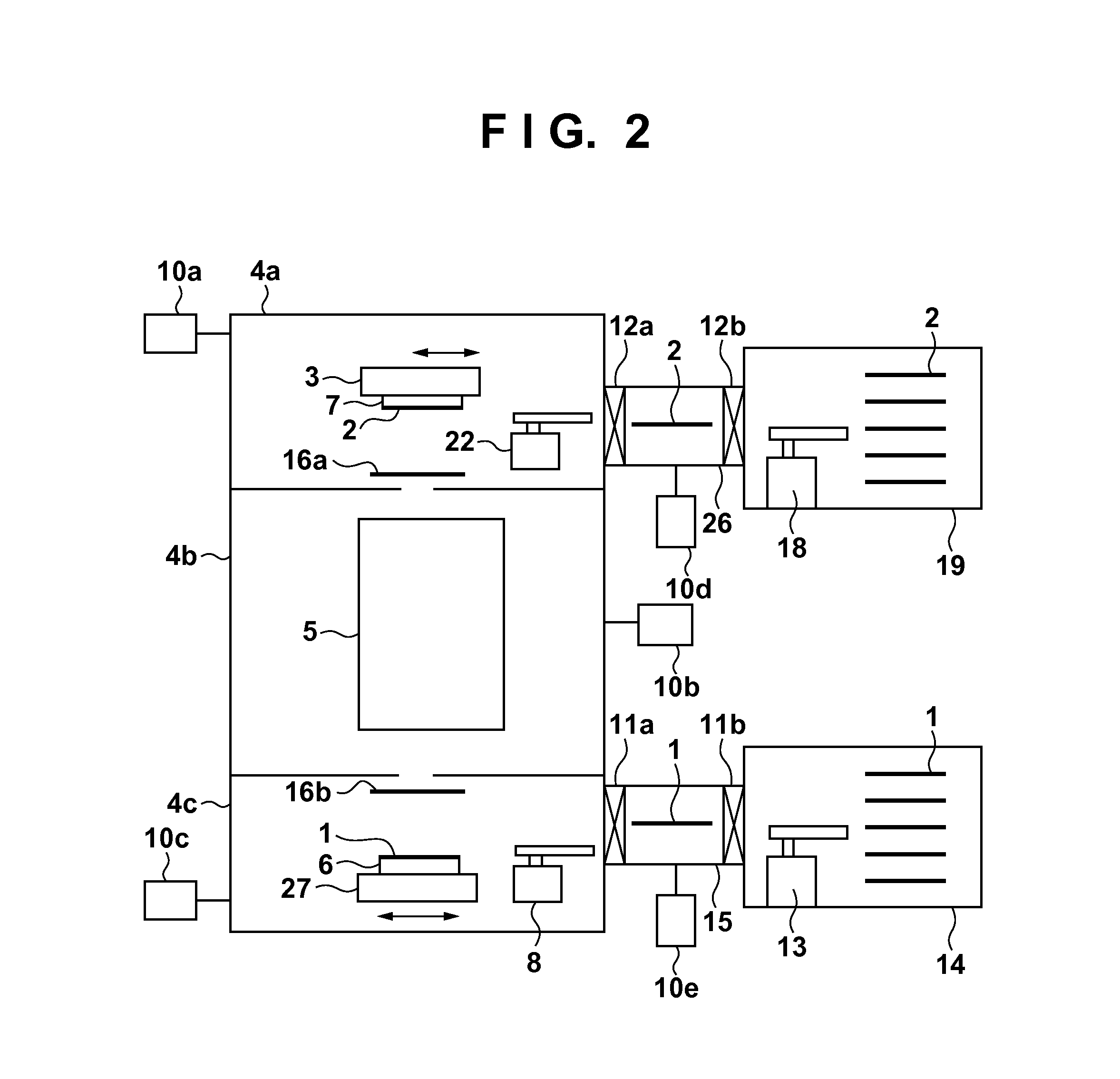
[0032]An EUV exposure apparatus which exposes a substrate by using extreme ultraviolet light (EUV light), to which the present invention is applied, will be explained with reference to FIG. 2. In FIG. 2, an electronic circuit pattern is formed on a reflective reticle (reflective original) 2. In the description of the present invention, a mask and reticle are synonymous. Especially when attention is paid to a pattern or multilayer film, the expression “mask” is used. When attention is paid to a substrate, the expression “reticle” is used.

[0033]A reticle chuck 7 holds and fixes the reticle 2. When performing EUV exposure processing, a reticle stage 3 moves the reticle 2 coarsely or finely in the scanning direction. A projection optical system 5 projection-exposes a wafer (substrate) 1 with EUV light reflected by the mask 2. A wafer chuck 6 holds and fixes the wafer 1. A wafer stage 27 moves the wafer 1 so that the wafer 1 can be moved coarsely and finely ...


PUM

PropertyMeasurementUnit
widthaaaaaaaaaa
thicknessaaaaaaaaaa
sizeaaaaaaaaaa

Abstract

A reflective original includes: a reflection layer which has a multilayer film configured to reflect extreme ultraviolet light; a base material configured to support the reflection layer; and a thermal diffusion layer interposed between the reflection layer and the base material, and configured to diffuse heat of the reflection layer. A heat capacity, per unit area, of a structure constituted by both the reflection layer and the thermal diffusion layer is not lower than 1.1 (J / (K·m2)).

Description

BACKGROUND OF THE INVENTION[0001]1. Field of the Invention[0002]The present invention relates to a reflective original, exposure method, and device manufacturing method.[0003]2. Description of the Related Art[0004]At present, the manufacture of semiconductor devices such as a DRAM and MPU has been studied and developed to implement devices having a line width of 22 nm or less in design rule. An exposure apparatus using extreme ultraviolet light (EUV) is prominent as an exposure apparatus used in this generation. An exposure apparatus generally irradiates, with light, a mask (also called an original or reticle) on which a circuit pattern is drawn. The exposure apparatus then reduces the image of the circuit pattern to, for example, ¼ by using a projection optical system, and projection-exposes the reduced image to a wafer coated with a photosensitive agent (resist). In actual exposure, if a particle is attached to the circuit pattern surface of a mask, the image of the particle is tr...

Claims


Application Information

Patent Timeline
Patent Type & Authority Patents(United States)
IPC IPC(8): G03F1/24G03F7/20
CPCG03F1/24G03F7/2002G03F1/22
Inventor YONEKAWA, MASAMIMIYAKE, AKIRA
Owner CANON KK
Why Eureka
Try Eureka