Eureka AIR delivers breakthrough ideas for toughest innovation challenges, trusted by R&D personnel around the world.

Thermal transfer printer

a technology of thermal transfer printer and ink sheet, applied in the field of thermal transfer printer, can solve the problems of excessive thermal energy applied to the ink sheet per unit area, inability to meet the needs of printing, etc., to suppress the generation of printing creases on the surface of printed matter, reduce the damage of the ink sheet

Active Publication Date: 2016-12-06
MITSUBISHI ELECTRIC CORP
View PDF28 Cites 0 Cited by
  • Summary
  • Abstract
  • Description
  • Claims
  • Application Information

AI Technical Summary

Benefits of technology

[0011]It is an object of the present invention to provide a thermal transfer printer that reduces damage on an ink sheet, making it possible to suppress generation of a printing crease in a surface of a printed matter due to damage on the ink sheet.
[0013]According to the present invention, even if the preceding image to be printed is such an image that generates damage on the ink sheet, the damage prediction part predicts damage on the ink sheet, and the preceding image is printed while control is exerted to suppress generation of the predicted damage on the subsequent print image based on the damage prediction. As a result, generation of damage such as a printing crease in the subsequent print image can be suppressed.

Problems solved by technology

This however involves initial costs required for preparation of a die to form a cylinder for new ink sheets, and management costs in response to the increased number of types of ink sheets.
If a dye-sublimation printer prints an image of a high density or makes prints at high speed, excessive thermal energy is applied to an ink sheet per unit area.
So, in response to application of thermal energy, the base material of the ink sheet is seriously damaged which may lead to shrinkage thereof.
So, if the ink sheet is rewound to find a region not having been used for printing, damage on the ink sheet generated during printing of a preceding image may adversely affect printing of a subsequent image.
By way of example, a printing crease may be formed or the ink sheet may fracture during printing of the subsequent image.
This adverse effect becomes noticeable especially if a plurality of images is formed by using a large-sized ink sheet.
However, this may complicate a print sequence.
If this means determines that the ink sheet is seriously damaged, a damaged picture block of the ink sheet is not used by rewinding the ink sheet, but other part of the ink sheet is used for printing.
However, this technique may make part of the ink sheet left unused become useless, generating a fear of increase of operational costs.

Method used


Image

  • Thermal transfer printer
  • Thermal transfer printer
  • Thermal transfer printer

Examples


first preferred embodiment

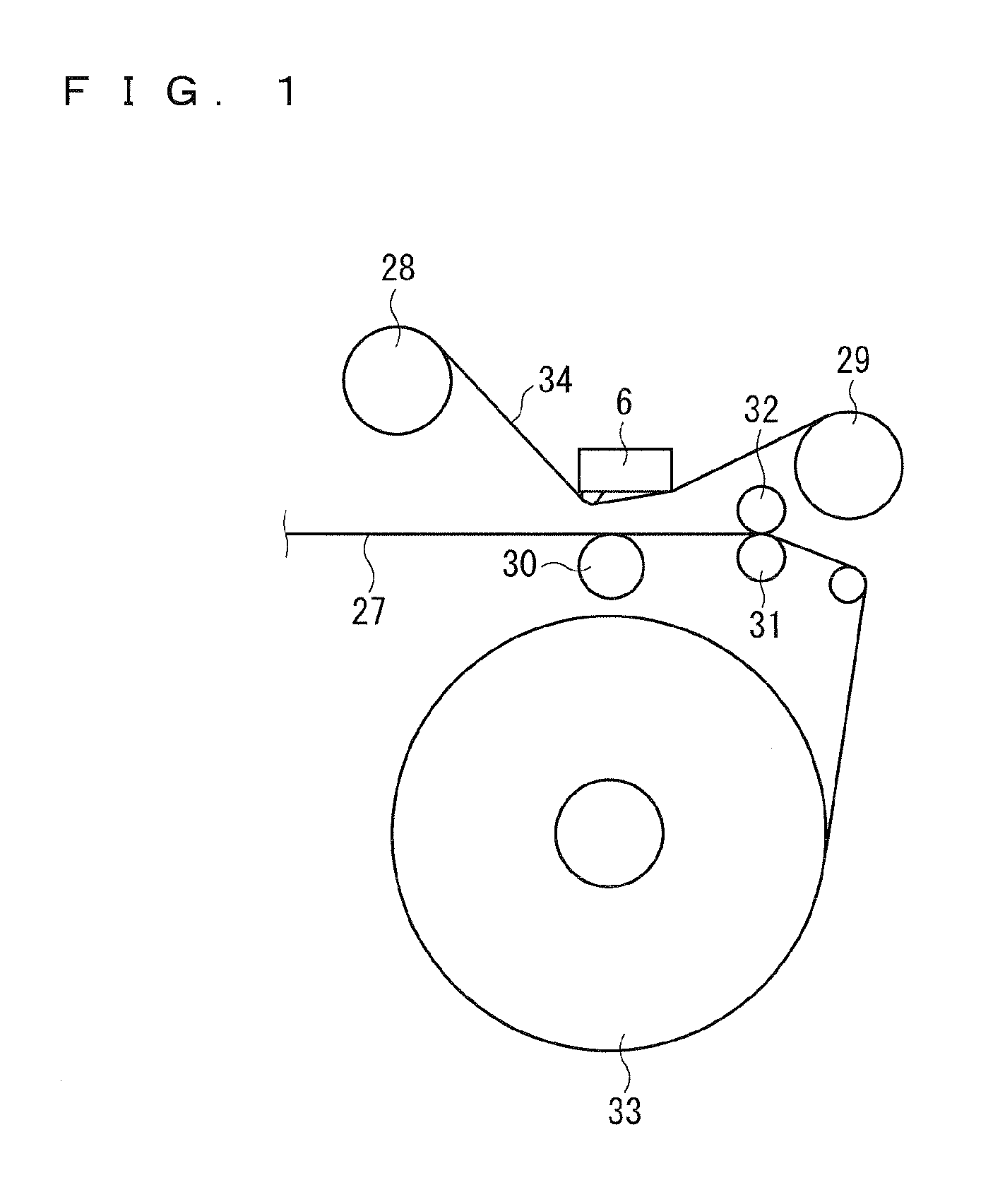
[0022]FIG. 1 shows the structure of a thermal transfer printer of a first preferred embodiment. An ink sheet 34 wound around ink bobbins 28 and 29, and a sheet of paper 27 wound around a paper roll 33, contact each other under pressure between a thermal head 6 and a platen roller 30. The thermal head 6 heats the ink sheet 34 to transfer ink applied to the ink sheet 34 onto the sheet of paper 27 being a target object of transfer. The sheet of paper 27 is conveyed by a grip roller 31 contacting a pinch roller 32 under pressure.

[0023]The grip roller 31 is driven by a grip roller-specific motor 11 (FIG. 3). A cam 10 (FIG. 3) is provided in the thermal head 6. The thermal head 6 is placed at a fixed position that can be controlled in response to the angle of rotation of the cam 10.

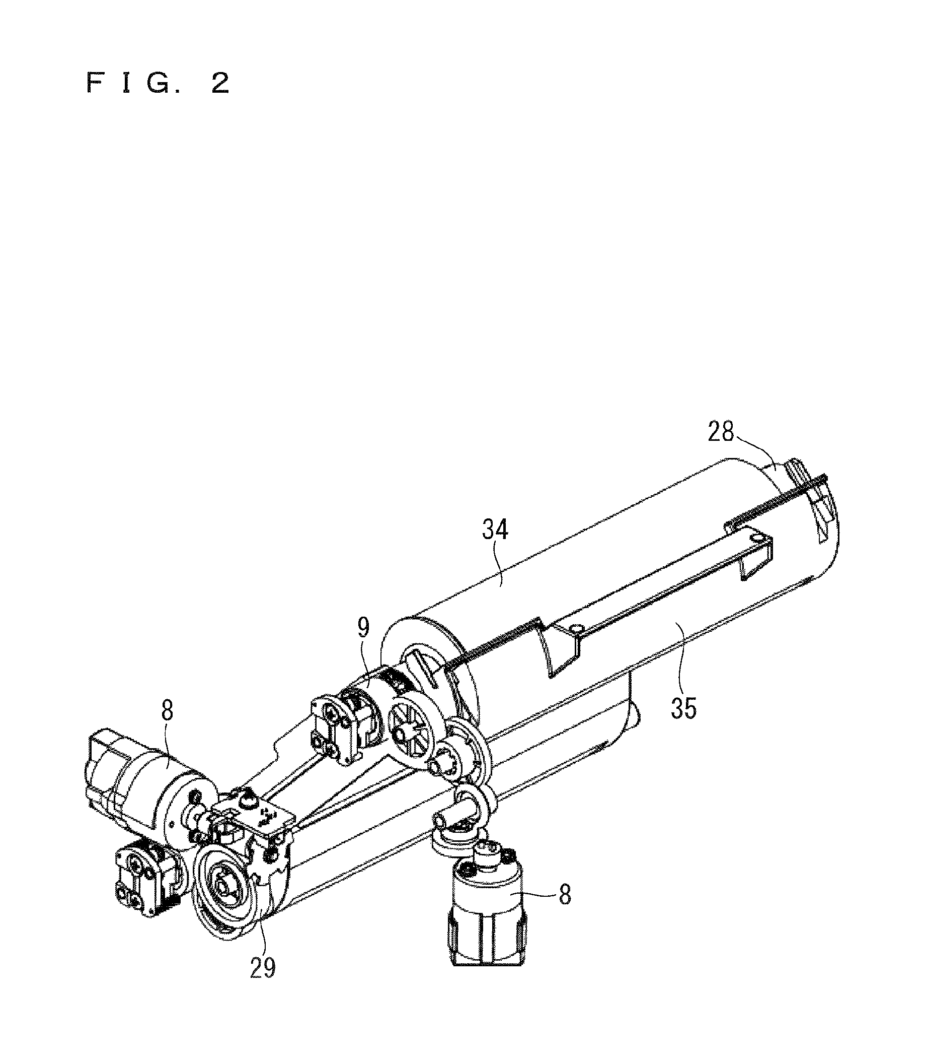
[0024]FIG. 2 shows a mechanism of conveying the ink sheet 34. The ink bobbins 28 and 29 are driven by an ink bobbin-specific motor 8. An ink cassette 35 housing the ink sheet 34 is attached to the ink bobbin 28...

second preferred embodiment

[0049]Like that of the first preferred embodiment, a thermal transfer printer of a second preferred embodiment includes a damage prediction part and a print control part. The structure, the basic print operation, and the damage prediction part of the thermal transfer printer of the second preferred embodiment are the same as those of the first preferred embodiment, so they will not be described again. In the second preferred embodiment, the print control part includes a print density controller that controls the density of a print image.

[0050]A print density is controlled by changing a reference table shown in FIG. 7. As is already described above, the reference table contains the gradation value of print data and the density of a print image in association with each other. It is assumed that the reference table generally determines the OD value based on a curve 20a. If the damage prediction part determines that damage will be generated, the print density controller changes the basi...

third preferred embodiment

[0053]Like that of the first preferred embodiment, a thermal transfer printer of a third preferred embodiment includes a damage prediction part and a print control part. The structure, the basic print operation, and the damage prediction part of the thermal transfer printer of the third preferred embodiment are the same as those of the first preferred embodiment, so they will not be described again. In the third preferred embodiment, the print control part includes a tension controller that controls tension on the ink sheet 34.

[0054]The ink sheet 34 receives tension applied to part thereof extending between the ink bobbin 29 toward which the ink sheet 34 is rolled up and the thermal head 6, and tension applied to part thereof extending between the thermal head 6 and the ink bobbin 28 to feed the ink sheet 34. In the instant specification, tensions applied to these parts are called roll-up tension and feed tension respectively. In the instant specification, “tension” is an inclusive ...


PUM


Abstract

A thermal transfer printer is capable of printing a plurality of images from one picture block of an ink sheet. The thermal transfer printer includes a damage prediction part that makes prediction of damage on a subsequent print image to be generated by printing of a preceding image by predicting damage on the ink sheet to be generated by printing of the preceding image, and a print control part that prints the preceding image while exerting control to suppress generation of the predicted damage on the subsequent print image based on the damage prediction.

Description

BACKGROUND OF THE INVENTION[0001]Field of the Invention[0002]The present invention relates to a thermal transfer printer and more specifically, to a thermal transfer printer capable of printing a plurality of images from one picture block of an ink sheet.[0003]Description of the Background Art[0004]Generally, a thermal transfer printer transfers ink in each line of an ink sheet onto a sheet of paper by conveying the ink sheet and the sheet of paper contacting each other under pressure between a thermal head and a platen roller, and at the same time, by controlling generation of heat in the thermal head. Generally, images of three color components including Y (yellow), M (magenta) and C (cyan) are placed one above the other and transferred, and thereafter, an OP (overcoat) layer is transferred, thereby enhancing resistance to whether and resistance to fingerprints of a printed matter.[0005]Regarding a thermal transfer printer is for use in printing of photographs, it is assumed that ...

Claims


Application Information

Patent Timeline
Patent Type & Authority Patents(United States)
IPC IPC(8): B41J2/325
CPCB41J2/325B41F16/00B41F33/00
Inventor TERAUCHI, SHUHEITAKESHITA, TOMOYUKI
Owner MITSUBISHI ELECTRIC CORP
Why Eureka
Eureka Blog
Learn More