Pneumatic tire

a technology of pneumatic tires and pneumatic cylinders, which is applied in the direction of tyre parts, vehicle components, transportation and packaging, etc., can solve the problems of limited durability, high cost of filling the entire tire cavity with foam, and noise generation of tires when driving, so as to reduce noise and/or vibration, good ventilation properties, and good compromise between material cos

Active Publication Date: 2021-06-10
THE GOODYEAR TIRE & RUBBER CO
View PDF7 Cites 0 Cited by
  • Summary
  • Abstract
  • Description
  • Claims
  • Application Information

AI Technical Summary

Benefits of technology

[0012]In an embodiment, the noise damping foam strip material is an open cell foam strip material. Open cell dampening material is much more suitable for dampening noise and/or vibration than closed cell foam material. In particular, an acoustic attenuation of tire cavity resonance is supported by the noise damping features of the present invention. Open cell noise damping foam material shall however not be understood herein as covering fully reticulated foam which constitutes a three-dimensional net, substantially free of cells or cell walls. While such material may have relatively good ventilation properties it is not deemed to be best suitable for dampening noise. Moreover, the latter material is relatively expensive.
[0013]In another embodiment, the open cell noise damping material has a density ranging from 0.01 g/cm3 to 1 g/cm3, optionally from 0.02 g/cm3 to 0.5 g/cm3. Such material has turned out to be of particular interest.
[0014]In another embodiment, the open cell foam strip material comprises from 55% to 95% (or preferably from 60% to 90%) open cells (of all cells) in the material. An open cell can be understood as a cell having at least one aperture. In other words, open cells are not fully closed or not fully enclosed by a cell wall. Closed cell foam does not fall into the above range as most cells of this foam type are closed. Fully or almost fully reticulated foam does not fall under that range either as it has almost no walls and constitutes rather an open grid. Whether cells are open or not (i.e. closed) can for instance be determined by light microscopy, SEM or NMR. Cell sizes could typically range from 10 μm to 1 mm (maximum diameter).
[0015]In still another embodiment, a first layer attached to the inne

Problems solved by technology

Tires generate noise when driving.
However, relatively thick layers result in internal strains in the foam material due to flexing and bending, thereby resulting in limited durability a

Method used


Image

  • Pneumatic tire
  • Pneumatic tire
  • Pneumatic tire

Examples


Embodiment Construction

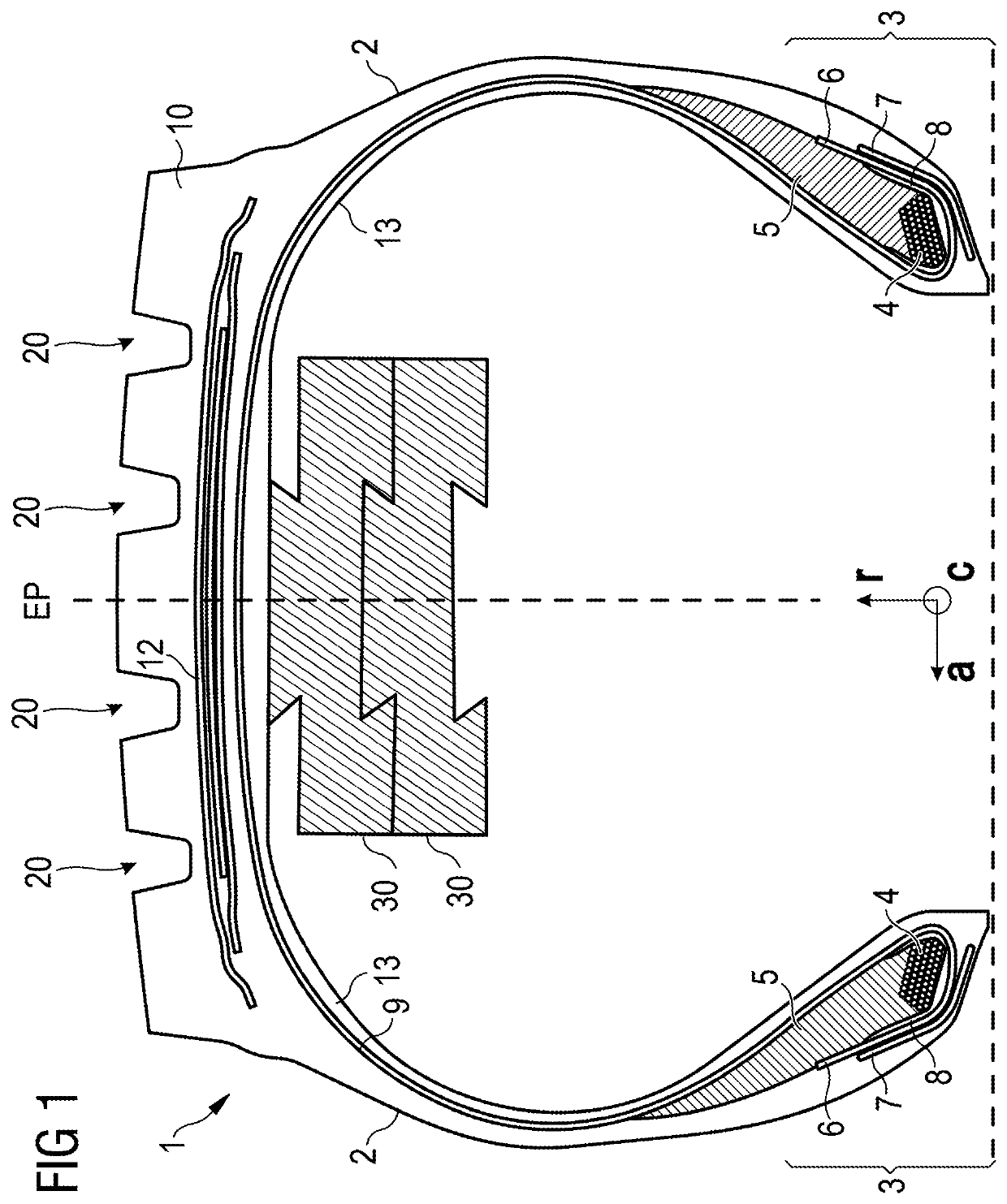
[0058]FIG. 1 is a schematic cross-section of a bus or truck tire 1. The tire 1 has a tread 10, an innerliner 13, a belt structure comprising a plurality of belt plies 12, a carcass ply 9, two sidewalls 2, and two bead regions 3 comprising bead filler apexes 5 and beads 4. The carcass ply 9 includes a pair of axially opposite end portions 6, each of which is associated with a respective one of the beads 4. Each axial end portion 6 of the carcass ply 9 may be turned up and around the respective bead 4 to a position to anchor each axial end portion 6. The turned-up portions 6 of the carcass ply 9 may engage the axial outer surfaces of two flippers 8 and axial inner surfaces of two chippers 7. As shown in FIG. 1, the example tread 10 may have four circumferential grooves 20, each groove essentially defining a U-shaped opening in the tread 10. In accordance with a first embodiment of the invention the tire 1 comprises two (stacked) interconnected layers 30 of a noise damping foam strip m...


PUM


Abstract

In a first aspect of the invention, the invention is directed to a pneumatic tire comprising two spaced apart bead portions, a tread portion, a pair of sidewalls extending radially inward from axially outer edges of the tread portion to join the respective bead portions, the axially outer edges of the tread portion defining a tread width, a carcass, an innerliner covering the carcass and defining a tire cavity, and multiple layers of foam strip material attached on top of each other to the innerliner within the tire cavity in an area radially below the tread portion, wherein at least two of the layers are interlocked to each other along their length so as to hold the layers together in a radial direction.

Description

[0001]This application claims benefit of U.S. Provisional Patent Application Ser. No. 62 / 943,413, filed on Dec. 4, 2019. The teachings of U.S. Provisional Patent Application Ser. No. 62 / 943,413 are incorporated herein by reference in their entirety.FIELD OF THE INVENTION[0002]The present invention is directed to a pneumatic tire comprising noise dampening foam strip material.BACKGROUND[0003]Tires generate noise when driving. It is known in the art that at least a part of that noise may be dampened by including foam material within the tire cavity for dampening tire cavity noise. An example of such a noise dampening material is given in United States Patent Publication No. 20120125507 A1 in which a single layer of rubber foam is applied to the innerliner of a tire. However, relatively thick layers result in internal strains in the foam material due to flexing and bending, thereby resulting in limited durability as fatigue cracks may occur. In other examples, such as in United States ...

Claims


Application Information

Patent Timeline
IPC IPC(8): B60C19/00
CPCB60C19/002
Inventor NICULA, ADRIAN FLORINVAISSAUD, JULIEN ALEXANDREMAUS, PETER JOHANN CORNELIUSDUCHENE, BAUDOUINBASTIN, PIERRE JOSEPH CHRISTIANLECLERC, PAUL
Owner THE GOODYEAR TIRE & RUBBER CO
Why Eureka
Try Eureka