
Free direct escapement mechanism for a timepiece

Pending Publication Date: 2021-06-10
FREYMOND ERIC
View PDF0 Cites 0 Cited by
  • Summary
  • Abstract
  • Description
  • Claims
  • Application Information

AI Technical Summary

Benefits of technology

The invention proposes a new mechanism for a regulating organ, which allows for a small angle of lift and a maximum rotational amplitude of up to 300°. This mechanism includes a locking device that requires only one locking pallet and is simple and compact. The mechanism is also self-starting, meaning it automatically calibrates and adjusts to the weight of the regulating organ. This allows for effective impulsion at a reduced cost and complexity.

Problems solved by technology

Their limitations, which are equally well known, are mainly a propensity to disturb the isochronism of the oscillations of the regulating organ due to the successive shocks and friction between the anchor and the regulating organ on the one hand and the anchor and the escapement wheel on the other, as well as a low mechanical efficiency, mainly for the same reasons.
However, the angle of lift of the Robin anchor is very small (about 5°) compared to the classical Swiss anchors (about 15°), which makes it difficult to apply the usual solution of securing the latter by guard pin and plate.
However, these Robin escapement mechanisms and associated safety devices are delicate to implement, so much so that they have never experienced massive commercial and industrial development, which their intrinsic technical performance could justify.

Method used


Image

  • Free direct escapement mechanism for a timepiece
  • Free direct escapement mechanism for a timepiece
  • Free direct escapement mechanism for a timepiece

Examples


first embodiment

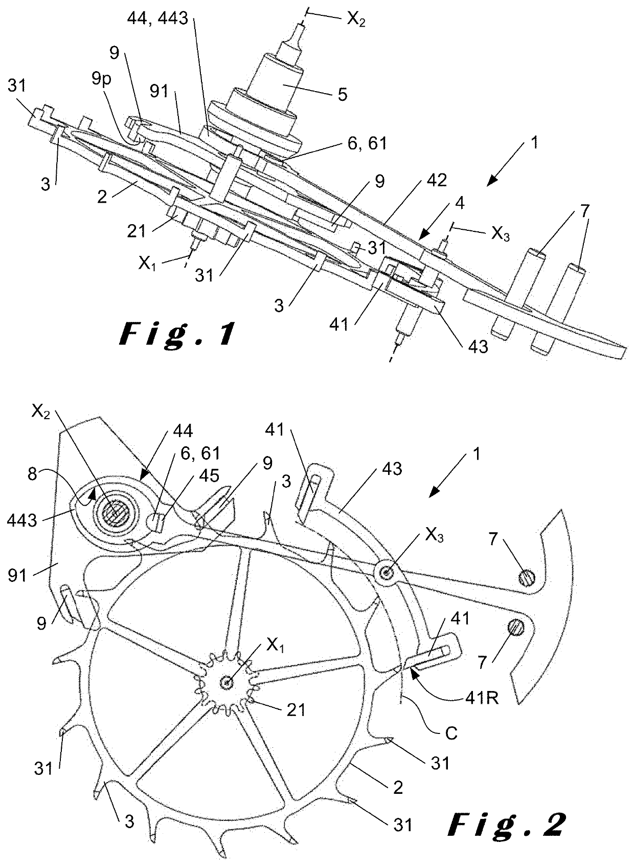
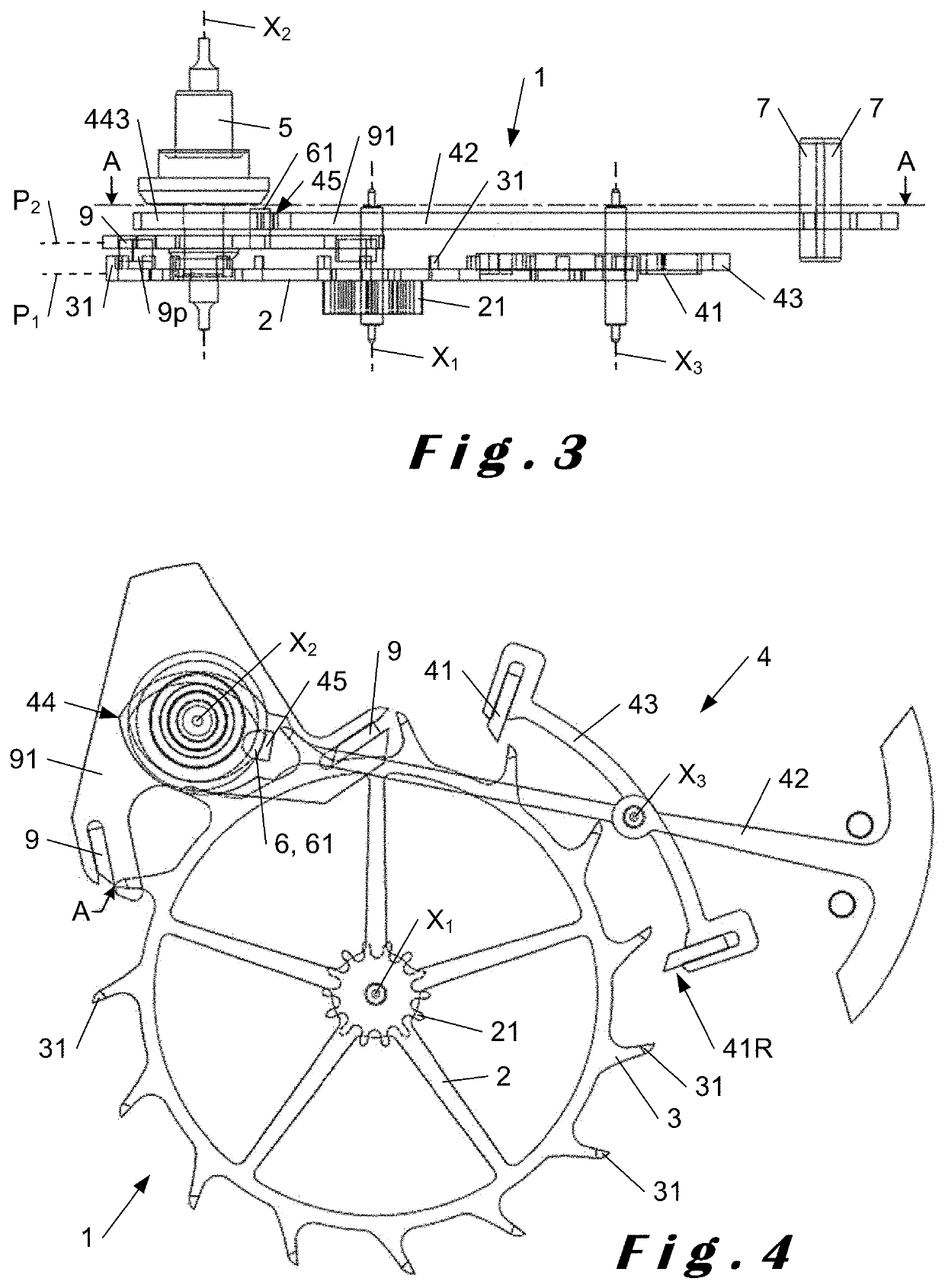
[0055]With reference first of all to the first embodiment, concerning the escapement mechanism 1 of the invention. It comprises an escapement wheel 2 extending in a plane P1 and provided with peripheral teeth 3 and rotatably mounted about an axis of rotation X1 perpendicular to this plane P1. Said teeth 3 define by their free ends a circular trajectory C during the rotation of the escapement wheel 2. In a conventional way, this escapement wheel 2 is associated with an escapement pinion 21 driven on a pivot of axis X1 common to the escapement wheel 2 and by which the latter can be coupled in use to the finishing gear train and the driving source of a watch movement in which the escapement mechanism 1 is integrated to maintain the oscillations of a regulating organ 5 of the movement, rotatably mounted around an axis of rotation X2.

[0056]In accordance with the invention, the teeth 3 of the escapement wheel 2 each have a protruding portion on the surface of the escapement wheel 2 to all...

second embodiment

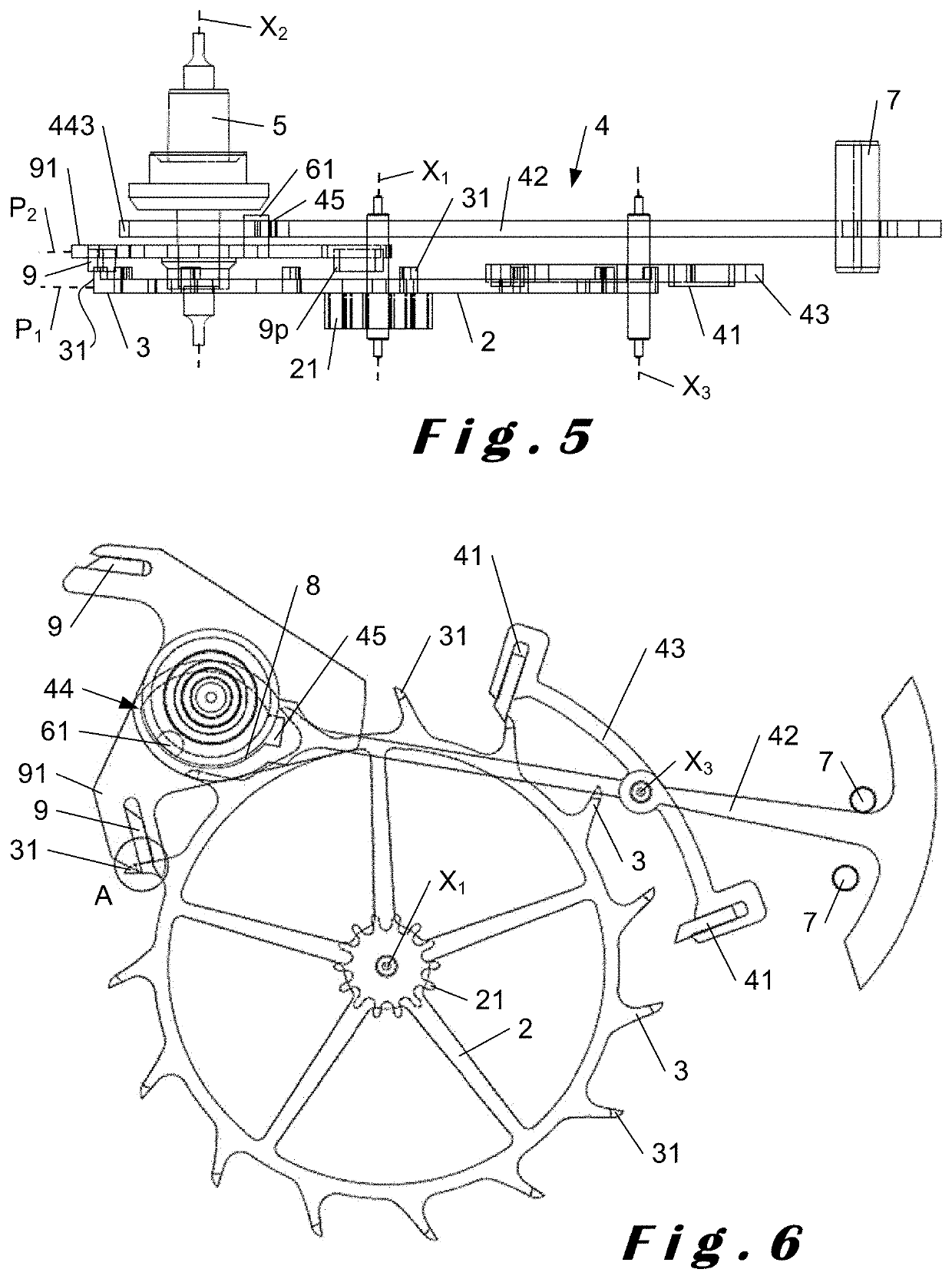
[0066]FIGS. 8 to 13 show the escapement mechanism according to the invention. This embodiment differs from the previous one in that it simplifies the locking device 4, which has only one locking pallet 4 whose movement is controlled by a trigger-type unlocking device. In addition, only one out of two teeth 3 of the escapement wheel 2 actually participates in the impulses by acting alternately on two parallel levels of impulses on either side of the plane P1 of the escapement wheel 2, as described below.

[0067]With reference to FIGS. 8 and 10 in particular, the escapement mechanism 1 of this second embodiment comprises an escapement wheel 2 extending in a plane P1 rotatably mounted about an axis of rotation X1 perpendicular to this plane P1. The escapement wheel 2 is provided with peripheral teeth 3 defining by their free ends a circular path C during the rotation of the escapement wheel 2. The number of teeth 3 of the escapement wheel 2 in this second embodiment is equal to twice tha...


PUM


Abstract

A direct impulse free escapement mechanism for a timepiece includes: an escapement wheel with peripheral teeth; a locking device including a locking pallet engaging an escapement wheel tooth in a locking position of the locking device; and a control pallet actuated by a pivoting regulating organ to engage a complementary unlocking organ of the locking device to release the locking device from the escapement wheel in an unlocking position at each alternation of the regulating organ. Also included are impulse pallets attachable to the regulating organ, cooperating on an impulse plane with a tooth of the escapement wheel to transmit a direct impulse to the regulating organ. The locking device is drawn by the escapement wheel in each locking position. The teeth of the escapement wheel and the impulse pallets are configured so the impulses occur outside the plane of the escapement wheel. A corresponding timepiece is also disclosed.

Description

TECHNICAL FIELD[0001]The present invention relates to the field of watchmaking. It concerns, more specifically, a free direct escapement mechanism.[0002]The invention also relates to a timepiece incorporating such an escapement mechanism.STATE OF THE ART[0003]Anchor escapements are certainly the most common type of escapement in mechanical watch mechanisms, at least in the so-called free escapement class. Associated with a regulating organ, typically of the pendulum or sprung balance assembly type, an anchor escapement makes it possible to maintain the oscillations of said regulating organ by transmitting to it by regular impulses, at a determined frequency, a fraction of the mechanical energy of the mechanical energy source of a said watch mechanism, usually comprising at least one barrel spring. At the same time, the escapement also allows the oscillations of the regulating organ to be counted and thus the time to be counted.[0004]Numerous variants of anchor escapements have been ...

Claims


Application Information

Patent Timeline
IPC IPC(8): G04B15/08G04B15/14
CPCG04B15/08G04B15/14G04B15/06G04B5/08
Inventor RENAUD, DOMINIQUE
Owner FREYMOND ERIC
Features
  • Generate Ideas
  • Intellectual Property
  • Life Sciences
  • Materials
  • Tech Scout
  • Unparalleled Data Quality
  • Higher Quality Content
  • 60% Fewer Hallucinations
Learn More