
Electric musical instrument system, control method and non-transitory computer readable medium thereof

a musical instrument and control method technology, applied in the field of electric musical instrument systems, can solve the problems of increasing the importance of power consumption management, and achieve the effect of simplifying the monitoring circuit of detected information and further suppressing power consumption in the power saving sta

Active Publication Date: 2021-06-10
ROLAND CORP
View PDF17 Cites 1 Cited by
  • Summary
  • Abstract
  • Description
  • Claims
  • Application Information

AI Technical Summary

Benefits of technology

The patent describes an electric musical instrument system that includes a device to transmit the sound from a musical instrument and a device to receive the sound. The system has a normal mode and a power-saving mode to save power. When returning from the power-saving mode, the system can suppress noise caused by the application of voltage to electronic components. The system can accurately determine whether to return from the power-saving mode by holding and transmitting the identifier of the sound receiving device. The system can also dynamically determine a frequency for transmitting the detected information, which simplifies the monitoring circuit and further reduces power consumption.

Problems solved by technology

On the other hand, as devices become cordless, the importance of power consumption management is increasing.

Method used


Image

  • Electric musical instrument system, control method and non-transitory computer readable medium thereof
  • Electric musical instrument system, control method and non-transitory computer readable medium thereof
  • Electric musical instrument system, control method and non-transitory computer readable medium thereof

Examples


modification example

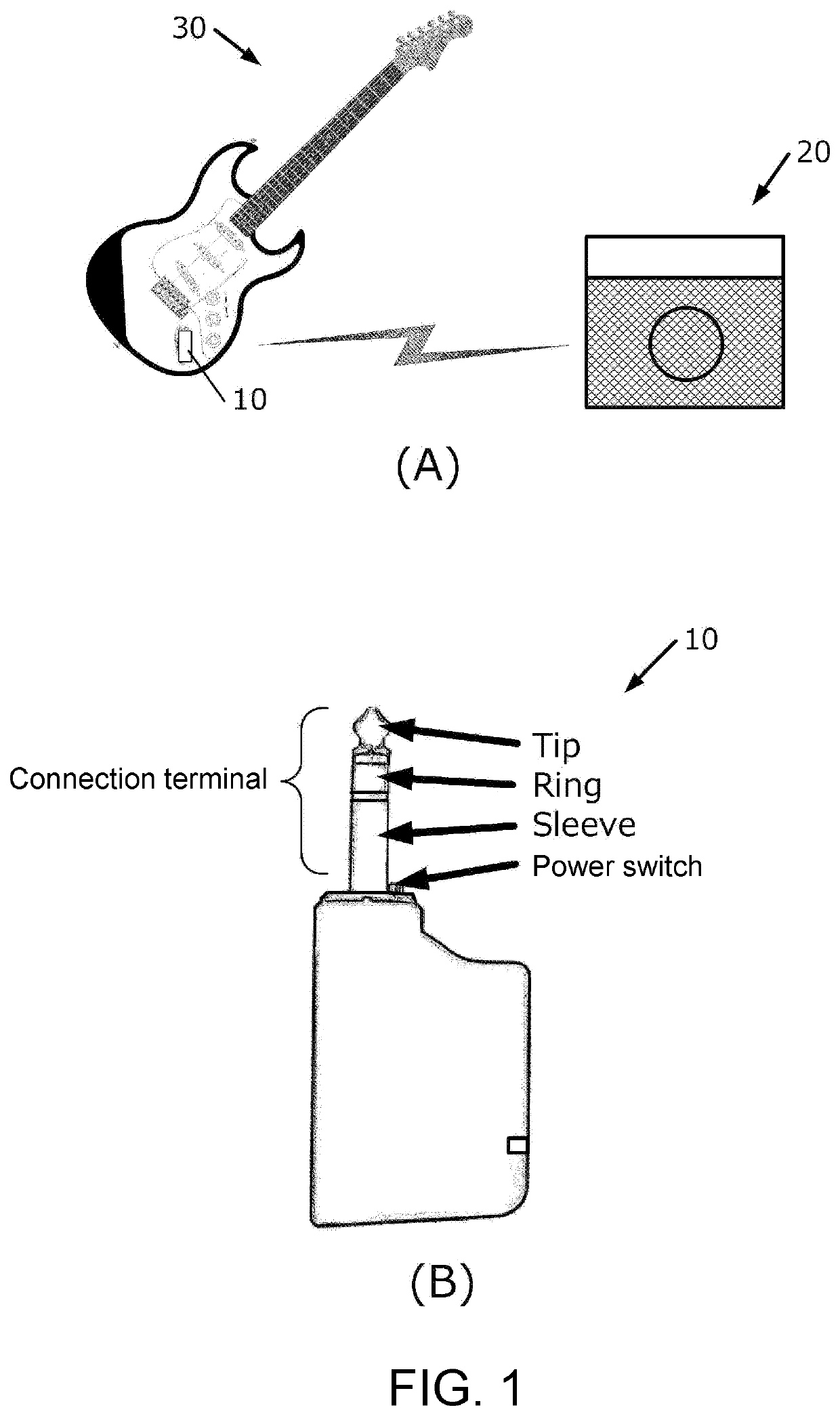
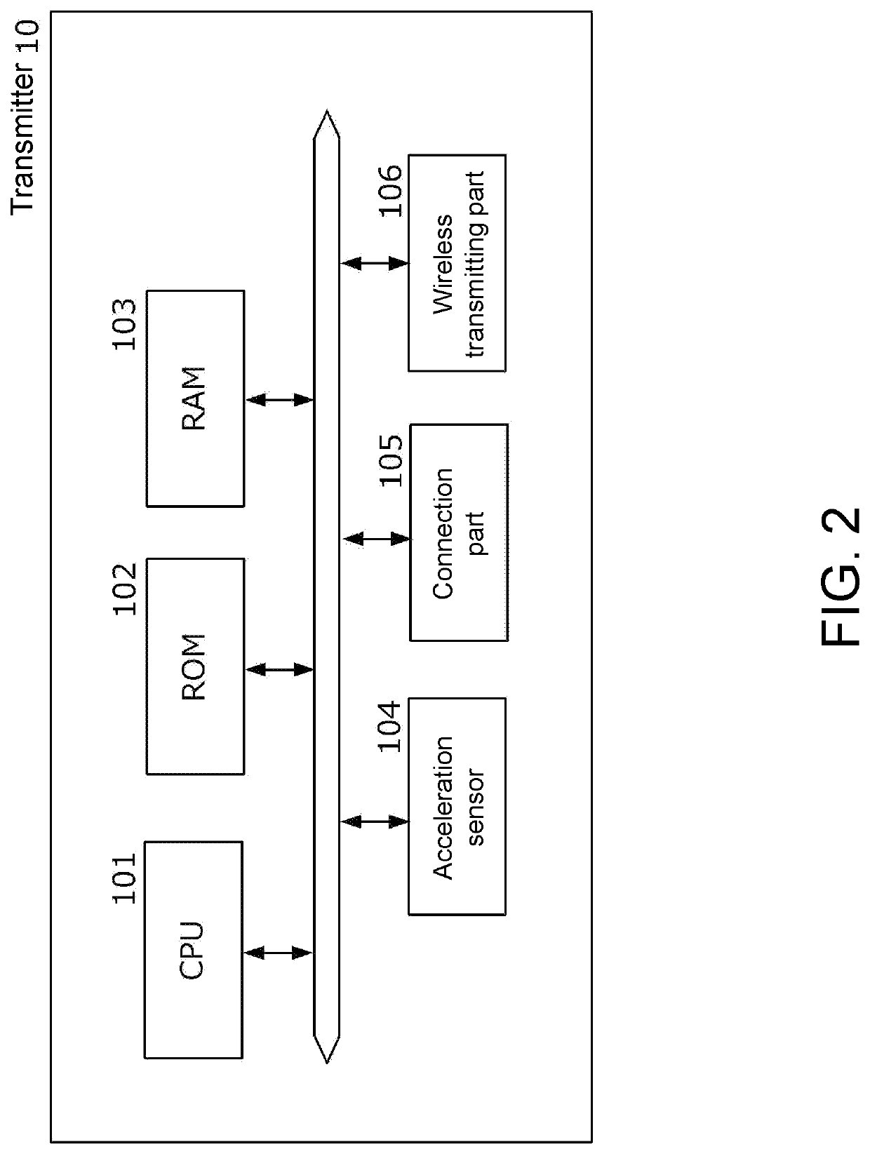
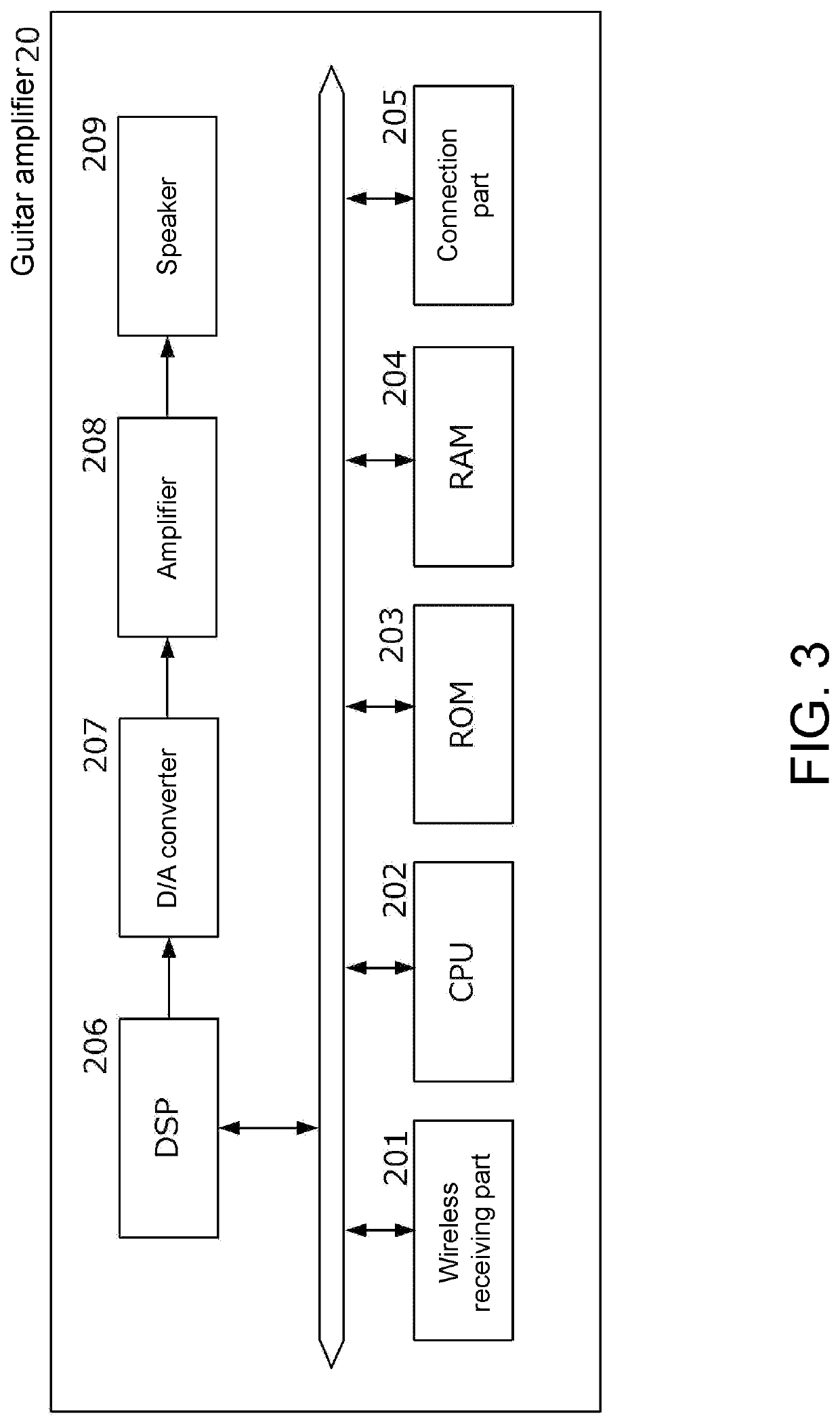
[0087]The above-described embodiment is merely an example, and the disclosure may be implemented with appropriate modifications without departing from the scope of the disclosure. For example, while the guitar amplifier has been shown as the musical sound receiving means in the description of the embodiment, a device other than this may also be connected. For example, it is also possible to combine an effector or the like. Also, while the transmitter and the guitar amplifier have been shown to be wirelessly connected with each other in the description of the embodiment, the connection may also be wired connection. Further, while the acceleration sensor has been used as the means for detecting the rocking of the musical instrument in the description of the embodiment, as long as the rocking of the musical instrument can be detected, other means (e.g., a distance sensor, a gyro sensor, a sensor that acquires another physical quantity, etc.) may also be used.


PUM


Abstract

Provided are an electric musical instrument system and a control method thereof. The electric musical instrument system includes a musical sound transmitting means having a first mode and a second mode that consumes less electric power than the first mode. The musical sound transmitting means has a detecting means for detecting rocking of a musical instrument and a transmitting means that transmits an audio signal emitted from the musical instrument to the musical sound receiving means in the first mode and transmits, when detecting rocking of the musical instruments, detected information to the musical sound receiving means in the second mode. The musical sound receiving means has a controlling means that processes the audio signal received in the first mode and cancels the second mode and changes the mode to the first mode when the detected information is received in the second mode.

Description

BACKGROUNDTechnical Field[0001]The disclosure relates to an electric musical instrument system.Related Art[0002]In the field of electronic musical instruments, systems in which a transmitter connected to a musical instrument transmits an audio signal to outside and an acoustic device such as an amplifier or an effector which receives the audio signal processes the audio signal have become widespread. In particular, transmitting the audio signal wirelessly eliminates the need for a cable connecting between the devices and greatly improves user convenience.[0003]On the other hand, as devices become cordless, the importance of power consumption management is increasing. For example, when an electronic musical instrument or an amplifier is driven by a battery, it is preferable to perform control to suppress power consumption during a period when no performance is going on.[0004]As an invention related thereto, Patent Document 1 discloses an electronic musical instrument wirelessly conne...

Claims


Application Information

Patent Timeline
Patent Type & Authority Applications(United States)
IPC IPC(8): G10H1/00G10H1/46
CPCG10H1/0083G10H1/46G10H2230/035G10H2220/401G10H2220/395G10H2240/321G10H3/186H04W52/0254H04W52/0258H04W52/028G06F1/3209G06F1/324G06F1/3215Y02D10/00Y02D30/70
Inventor UENO, MASATOASAKAWA, SHINJIYAMATE, HIROSHI
Owner ROLAND CORP
Learn More