

Image processing device, image processing method, and program recording medium
- Summary
- Abstract
- Description
- Claims
- Application Information
AI Technical Summary
Benefits of technology
Problems solved by technology
Method used
Image

Examples
first example embodiment
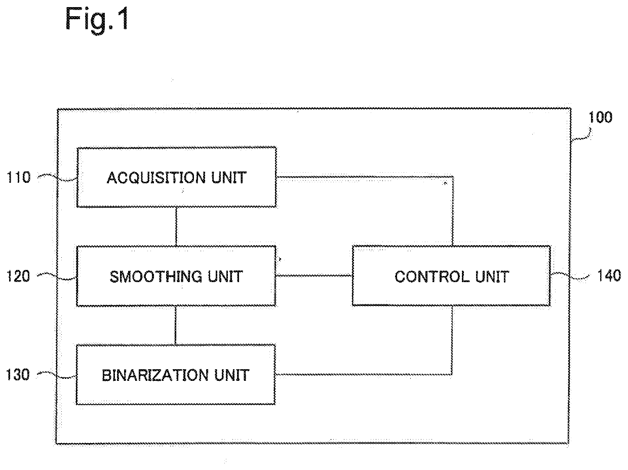
[0060]FIG. 1 is a block diagram illustrating a configuration of an image processing device 100 according to a first example embodiment of the present disclosure. The image processing device 100 includes at least an acquisition unit 110, a smoothing unit 120, a binarization unit 130 and a control unit 140. The image processing device 100 may be realized by a combination of a processor, hardware such as a memory, and software such as a program.
[0061]The acquisition unit 110 acquires an image. For example, the acquisition unit 110 acquires an image by receiving an input of digital data or an analog signal representing an image. In other words, “acquire an image” can also be said to acquire image data or an image signal. An image acquired by the acquisition unit 110 represents an image captured by a capturing device including, for example, a complementary metal-oxide-semiconductor (CMOS) image sensor, a charge coupled device (CCD) image sensor, and the like.
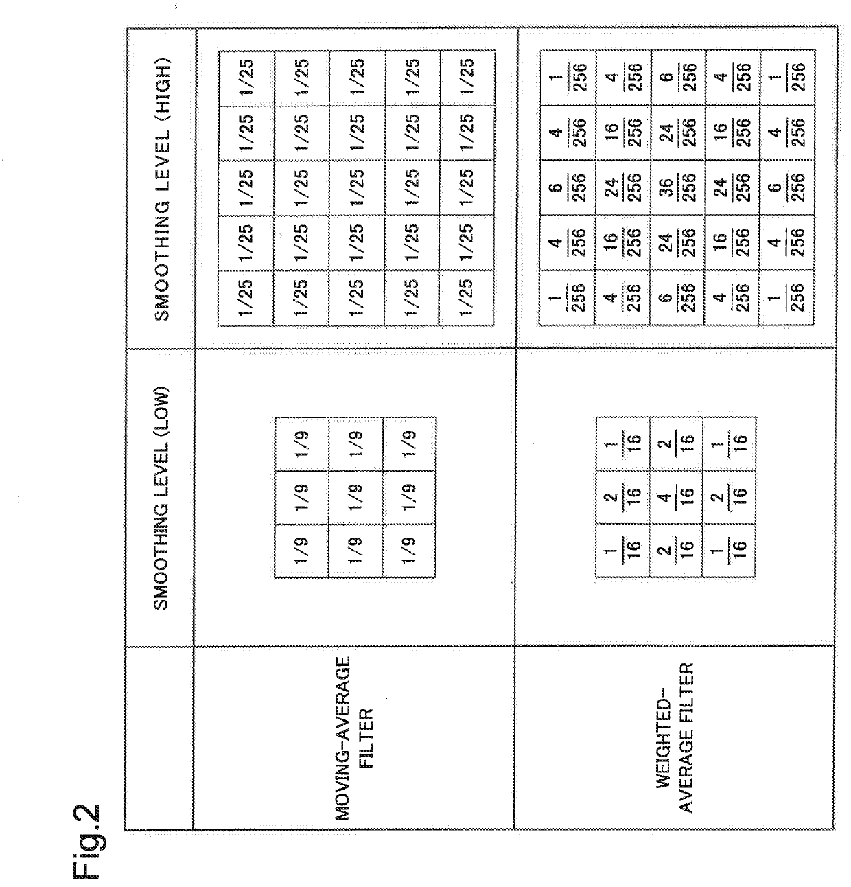
[0062]The smoothing unit 120 ...
second example embodiment
[0075]FIG. 5 is a block diagram illustrating a configuration of a character recognition device 200 according to a second example embodiment of the present disclosure. The character recognition device 200 includes a character recognition unit 210 and a control unit 220 in addition to the acquisition unit 110, the smoothing unit 120, and the binarization unit 130 that are the same as those in the first example embodiment. It can also be said that the character recognition device 200 is an image processing device having a character recognition function.
[0076]Note that, in the present example embodiment, the same term as the term described in the first example embodiment is used to represent the same as in the first example embodiment except for that the term particularly has a definition or description. In addition, a component provided with the same reference numeral as that in the first example embodiment has at least the same configuration as that in the first example embodiment.
[00...
third example embodiment
[0094]FIG. 8 is a block diagram illustrating a configuration of a communication terminal 300 according to a third example embodiment of the present disclosure. The communication terminal 300 includes a control unit 310, an image processing unit 320, a storage unit 330, a communication unit 340, a user interface (UI) unit 350, and a camera unit 360. The communication terminal 300 is, for example, a mobile communication terminal such as a smartphone and a tablet terminal, but may not be necessarily limited to a mobile communication terminal.
[0095]The communication terminal 300 has a configuration corresponding to one example of the character recognition device 200 described in the second example embodiment. Further, in the present example embodiment, the same term as the term described in the first example embodiment or the second example embodiment is used to represent the same as in the first example embodiment or the second example embodiment except for that the term particularly h...
PUM
 Abstract
Description
Claims
Application Information