Pneumatically coupled direct drive fluid control system and process

a direct drive fluid and control system technology, applied in process and machine control, instruments, prostheses, etc., can solve problems such as reducing or increasing the pressure of gas

Active Publication Date: 2019-07-09
NEWIV MEDICAL CORP
View PDF68 Cites 3 Cited by
  • Summary
  • Abstract
  • Description
  • Claims
  • Application Information

AI Technical Summary

Benefits of technology

The present invention is about a fluid control system that uses pneumatic power to control fluid delivery. It is reliable and can handle changes in conditions. It includes a simple actuating mechanism and a low-pressure control system, which overcomes the limitations of prior art systems. Additionally, the system has an improved air detection and elimination mechanism that prevents the negative effects of air bubbles. This mechanism uses a hydrophobic filter material and a one way valve to remove air from the system. Overall, the invention solves the problem of air bubbles and provides a more stable and reliable fluid control system.

Problems solved by technology

Reciprocal motion of the reciprocating element, e.g., the piston or bellows, under control of the drive motor, imposes positive or negative volume differences on the gas in the gas-side reservoir, which results in a decrease or an increase in the pressure of the gas.

Method used


Image

  • Pneumatically coupled direct drive fluid control system and process
  • Pneumatically coupled direct drive fluid control system and process
  • Pneumatically coupled direct drive fluid control system and process

Examples


examples

[0137]

referenceFLOW RATE mL / hr6060606600valuereferenceDURATION min120120120120240valuesample dataNOW13:30:0013:30:0013:30:0013:30:0013:30:00sample dataSTART_TIME12:30:0012:30:0012:30:0012:30:0012:30:00sample dataTARGET VOL (μL)120,000120,000120,00012,0002,400,000sample dataTARGET TIME7,2007,2007,2007,20014,400(sec)calculatedOWED VOL (μL)60,00060,00060,0006,000600,000sample dataDELIVERED VOL60,00059,50061,0005,990600,000(μL)referenceERROR %0.00%−0.83%1.67%−0.17%0.00%valuesample dataSTROKE VOL (μL)1,0001,0001,0001,0001,000sample dataMOTORSTEPS400400400400400calculatedTARGET STROKE60,00030,000120,000594,0006,000TIME (msec)calculatedSTEP TIME (msec)150753001,48515

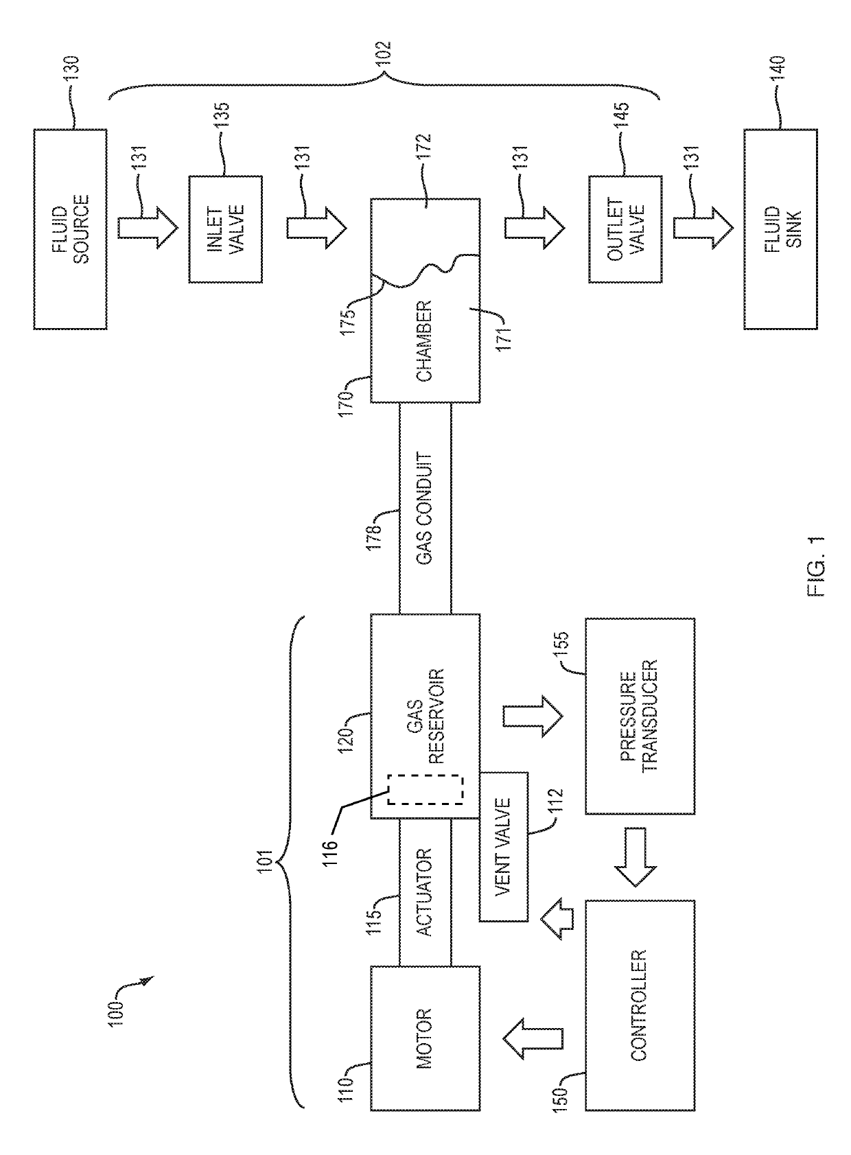
[0138]During the state DELIVER 827, the motor drive operates forward every TARGET STROKE TIME. If the fluid is leaving the fluid-side chamber 172 at the same rate as the gas-side chamber 171 volume is changing, then there is no change in driving pressure of the fluid.

[0139]If the flow of fluid towards the sink is slower than th...


PUM


Abstract

A fluid control system for delivery of a liquid includes a pneumatic drive that incorporates a linear actuator to effect known volume changes in a gas reservoir. The gas reservoir is in fluid communication with a gas-side reservoir that is separated from a fluid-side reservoir by a flexible membrane. Movement of the linear actuator effects positive or negative volume differences on the gas in the gas-side reservoir, resulting in a decrease or increase in pressure of the gas that is transmitted to the fluid-side reservoir to draw fluid, primarily liquid, in from a source or deliver liquid out to a sink. In another aspect, a mechanism is provided for the detection and elimination of air bubbles in the fluid path.

Description

CROSS-REFERENCE TO RELATED APPLICATIONS[0001]This application is a divisional application of U.S. patent application Ser. No. 14 / 285,278 filed May 22, 2014, which, in turn, claims the benefit under 35 U.S.C. § 119(e) of U.S. Provisional Patent Application No. 61 / 826,863, filed May 23, 2013. Each of the aforementioned applications is incorporated by reference herein in its entirety.BACKGROUND[0002]Fluid flow control is an essential part of medical devices such as intravenous infusion pumps and enteral feeding systems. These fluid flow control systems must meet a complex and conflicting set of requirements, such as broad flow rate range, wide ranging fluid viscosity, inevitable presence of harmful amounts of gas, changing source pressure, changing patient pressure, variable patient line resistance, and a wide range of tubing configurations.[0003]Reliability and ability to detect fault conditions are critical features of such flow control devices. Low acquisition and maintenance costs ...

Claims


Application Information

Patent Timeline
Patent Type & Authority Patents(United States)
IPC IPC(8): A61M5/168A61M5/36A61M39/24A61M5/142A61M1/10A61M5/155A61M5/145A61M5/172A61M5/38
CPCA61M5/16831A61M5/1452A61M5/14224A61M5/155A61M5/16822A61M5/16854A61M5/16859A61M5/16881A61M5/365A61M39/24A61M1/106A61M2205/3379A61M5/14593A61M5/172A61M5/385A61M2005/14208A61M2005/14513A61M2039/242A61M2205/123A61M2205/128A61M2205/3306A61M2205/3331A61M2205/3337
Inventor CARLISLE, JEFFREY A.KUBA, LAWRENCE M.
Owner NEWIV MEDICAL CORP
Why Eureka
Try Eureka