
Monitor and Control of Tumbling Mill Using Measurements of Vibration, Electrical Power Input and Mechanical Power

Inactive Publication Date: 2017-08-10
EMERSON ELECTRIC US HLDG CHILE
View PDF21 Cites 4 Cited by
  • Summary
  • Abstract
  • Description
  • Claims
  • Application Information

AI Technical Summary

Benefits of technology

The present invention provides a better way to monitor the state of a grinding mill by using rotor dynamics to determine characteristics of the moving charge within the tumbler. This information can be used in combination with other types of sensor information, such as vibration or sound sensors, to get a more accurate and speedy measurement of the mill's operating condition. The invention improves the quality of monitoring the tumble mill by providing real-time information about the current state of the charge in the tumbler.

Problems solved by technology

Grinding in tumbling mills may be inefficient particularly where energy is wasted by impact that does not break particles.
Autogenous (AG) and semi-autogenous (SAG) mills often operate in an unstable state because of the difficulty in balancing the rate of replacement of large particles from the seed with the consumption of the charge.

Method used


Image

  • Monitor and Control of Tumbling Mill Using Measurements of Vibration, Electrical Power Input and Mechanical Power
  • Monitor and Control of Tumbling Mill Using Measurements of Vibration, Electrical Power Input and Mechanical Power
  • Monitor and Control of Tumbling Mill Using Measurements of Vibration, Electrical Power Input and Mechanical Power

Examples


Embodiment Construction

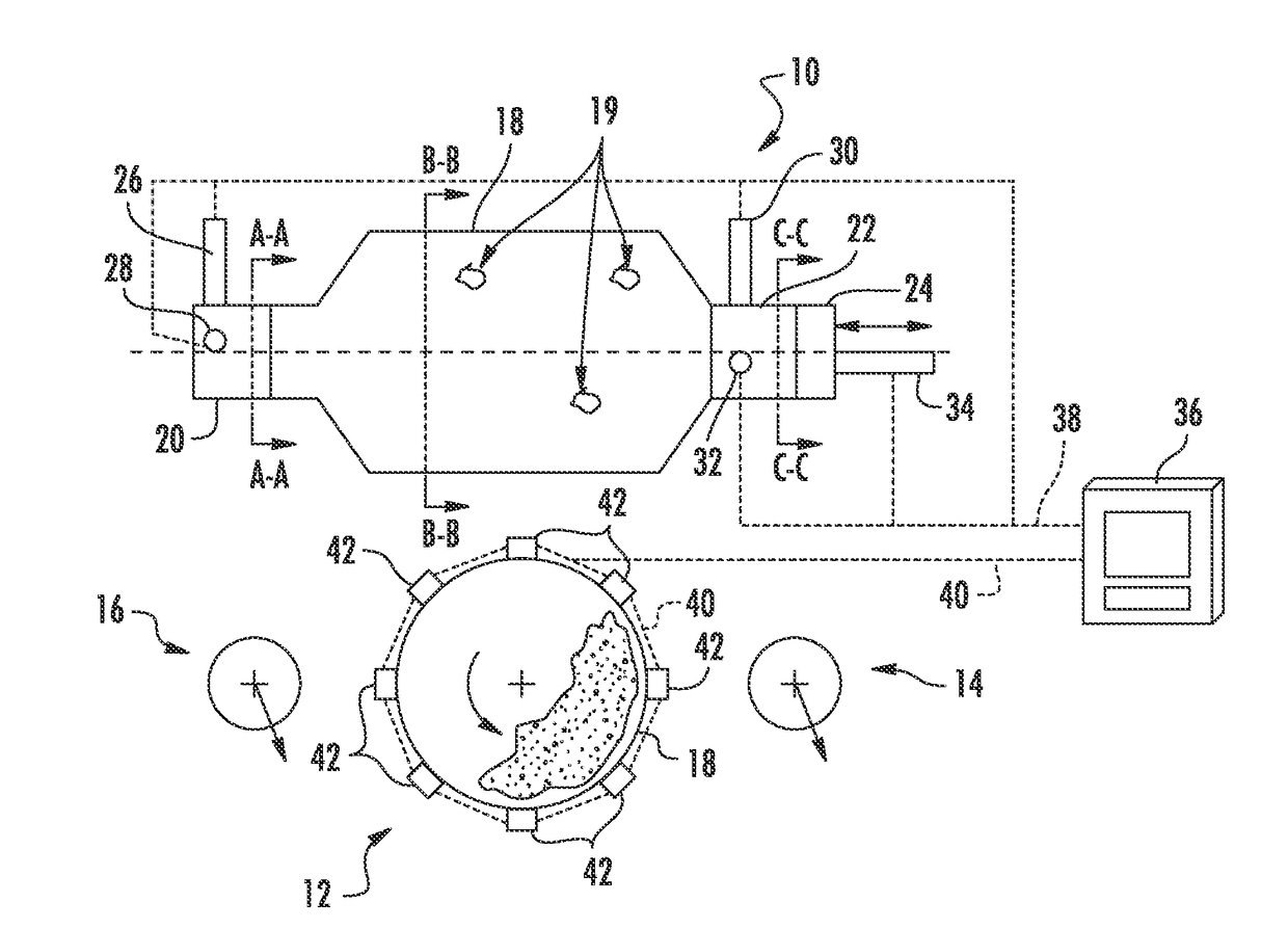
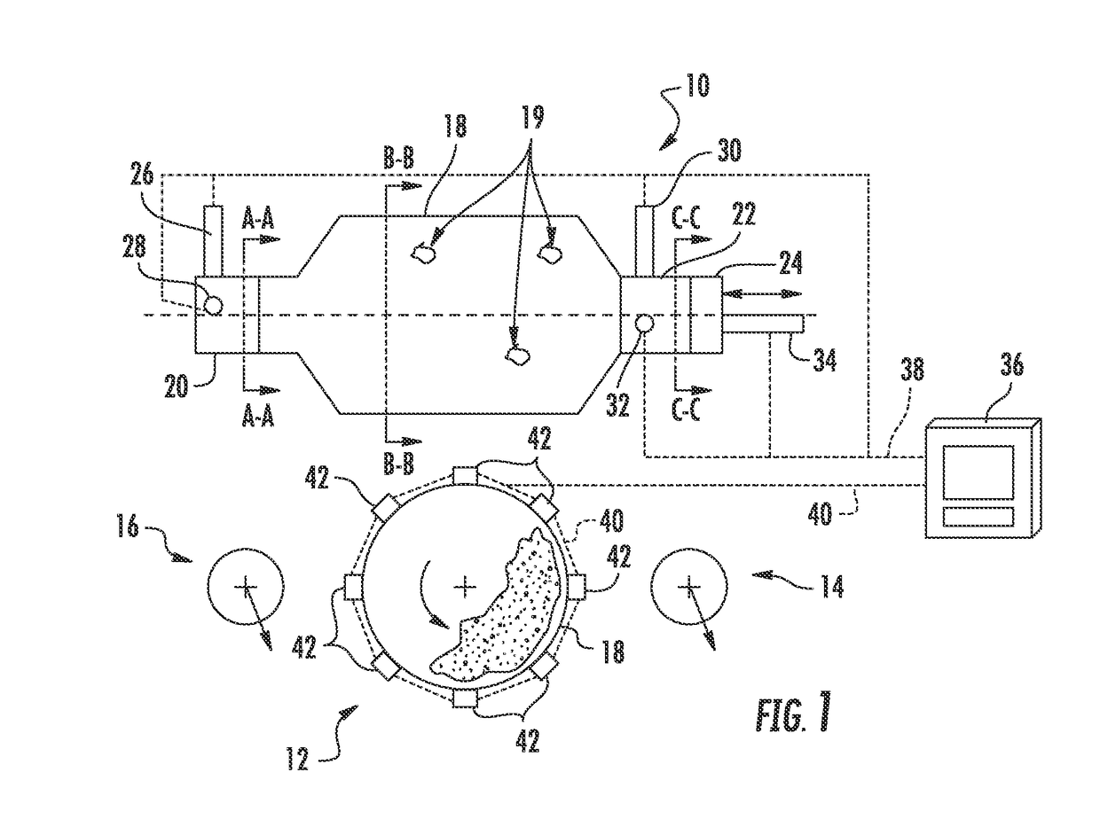
[0018]Referring to FIG. 1, a somewhat diagrammatic and schematic side view of a tumbling mill 10 is shown. Three sectional views are also shown in FIG. 1, section A-A, B-B and C-C. Section view A-A is also is also identified by the reference 16. Likewise, section B-B as identified by the reference 12 and section C-C is identified by the reference 14. The tumbling mill 10 includes a shell 18 that contains a charge of material to be tumbled and ground. For example, a rock mineral may be supplied to the shell 18 as a charge. The rock 19 and the charge will tumble against itself and the side of the shell 18 grinding itself into finer material. In a SAG mill, a supplemental material may be added to the charge to aid in the grinding process, such as steel balls.

[0019]The shell 10 is supported on two main bearings 20 and 22 and in addition a thrust bearing 24 is provided to resist thrust forces that may be generated by the shell 18 as it rotates. Vibration sensors 26 and 28 are provided on...


PUM


Abstract

An apparatus monitors a tumble mill and includes at least two vibration sensors mounted on a first main bearing and at least two vibration sensors mounted on a second main bearing of the mill. Sensors may be disposed radially with respect to the bearing. A vibration sensor is also connected to a thrust bearing of the mill oriented in a direction parallel to the rotational axis of the shell of the mill. A signal analyzer receives and analyzes signals from all vibration monitors on the bearings and displays an operating condition of the tumble mill. Additional vibration sensors may be mounted on the shell, and sensors may be provided to sense electrical power input and mechanical power output of the motors. In operation, the mill is loaded with a standard charge and operated at a standard rotational rate. The sensor data is analyzed and displayed when the mill is operating.

Description

PRIORITY[0001]This application claims priority to U.S. Patent Application 62 / 034,359 filed on Aug. 7, 2014, entitled Monitor and Control Tumbling Mill Using Vibration Inputs incorporated by reference herein in its entirety.FIELD[0002]The present invention relates to the field of tumbler mills and particularly relates to the monitoring and control of tumbler mills using vibration, electrical and power measurementsBACKGROUND AND SUMMARY OF INVENTION[0003]Grinding in tumbling mills may be inefficient particularly where energy is wasted by impact that does not break particles. Autogenous (AG) and semi-autogenous (SAG) mills often operate in an unstable state because of the difficulty in balancing the rate of replacement of large particles from the seed with the consumption of the charge. To control this process it is essential that real-time information be provided as to the current state of the charge in the tumbler. Past processes have used sensors on the shell of the tumbler and sens...

Claims


Application Information

Patent Timeline
IPC IPC(8): B02C17/18B02C25/00
CPCB02C25/00B02C17/1805
Inventor NOWER, DANIEL L.BOWERS, STEWART V.BASSETT, SCOTT T.GARVEY, III, RAYMOND E.DOSS, RANDAL M.SLEMP, MARK W.BANERJEE, TUHINSCHAFFER, MICHAEL
Owner EMERSON ELECTRIC US HLDG CHILE
Learn More