Biopotential measurement device and non-transitory computer readable medium

a technology of biopotential measurement and computer readable medium, which is applied in the field of biopotential measurement devices and non-transitory computer readable medium, can solve the problems of increasing the amount, tightening the memory capacity, and shortening so as to increase the amount of data, shorten the data saving time, and tighten the memory capacity

Pending Publication Date: 2021-07-01
AGAMA X CO LTD
View PDF8 Cites 0 Cited by
  • Summary
  • Abstract
  • Description
  • Claims
  • Application Information

AI Technical Summary

Benefits of technology

[0005]However, increasing the frequency increases the amount of data, which may tighten the memory capacity, shorten the data saving time, etc. Therefore, it is desired to reduce the amount of data while measuring a biopotential with a high precision.

Problems solved by technology

However, increasing the frequency increases the amount of data, which may tighten the memory capacity, shorten the data saving time, etc.
However, aspects of the non-limiting embodiments are not required to overcome the disadvantages described above, and aspects of the non-limiting embodiments of the present disclosure may not overcome any of the disadvantages described above.

Method used


Image

  • Biopotential measurement device and non-transitory computer readable medium
  • Biopotential measurement device and non-transitory computer readable medium
  • Biopotential measurement device and non-transitory computer readable medium

Examples


first exemplary embodiment

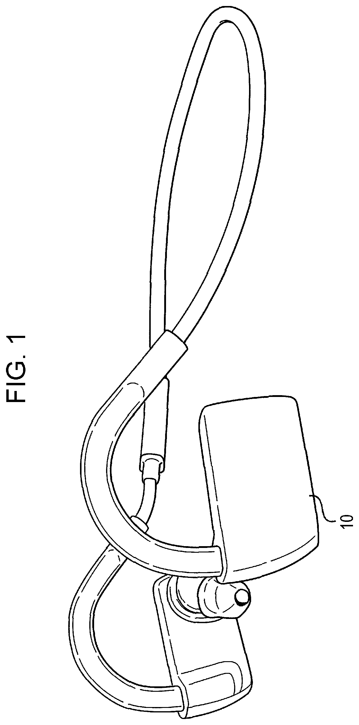
[0020]FIG. 1 illustrates an example of the appearance of a biopotential measurement device 10 according to a first exemplary embodiment.

[0021]By way of example, a simple electroencephalograph of an earphone type is applied to the biopotential measurement device 10 according to the present exemplary embodiment. The simple electroencephalograph may be an electroencephalograph which uses a single-channel (1-ch) dry electrode, for example. In this case, the biopotential measurement device 1 is mountable on the ears of a person to be measured, and acquires a biopotential from the external auditory meatus of the ears. Examples of the biopotential include a brain wave potential, a pulse wave potential, and a myoelectric potential. Examples of the biological body to be measured include a human. It should be noted, however, that the biological body to be measured may not be a human, and may be a dog, a cat, etc., for example.

[0022]Most simple electroencephalographs according to the related a...

second exemplary embodiment

[0071]In the first exemplary embodiment described above, one type of biopotential is selectively measured among a plurality of types of biopotentials. In the present exemplary embodiment, a plurality of types of biopotentials are measured concurrently.

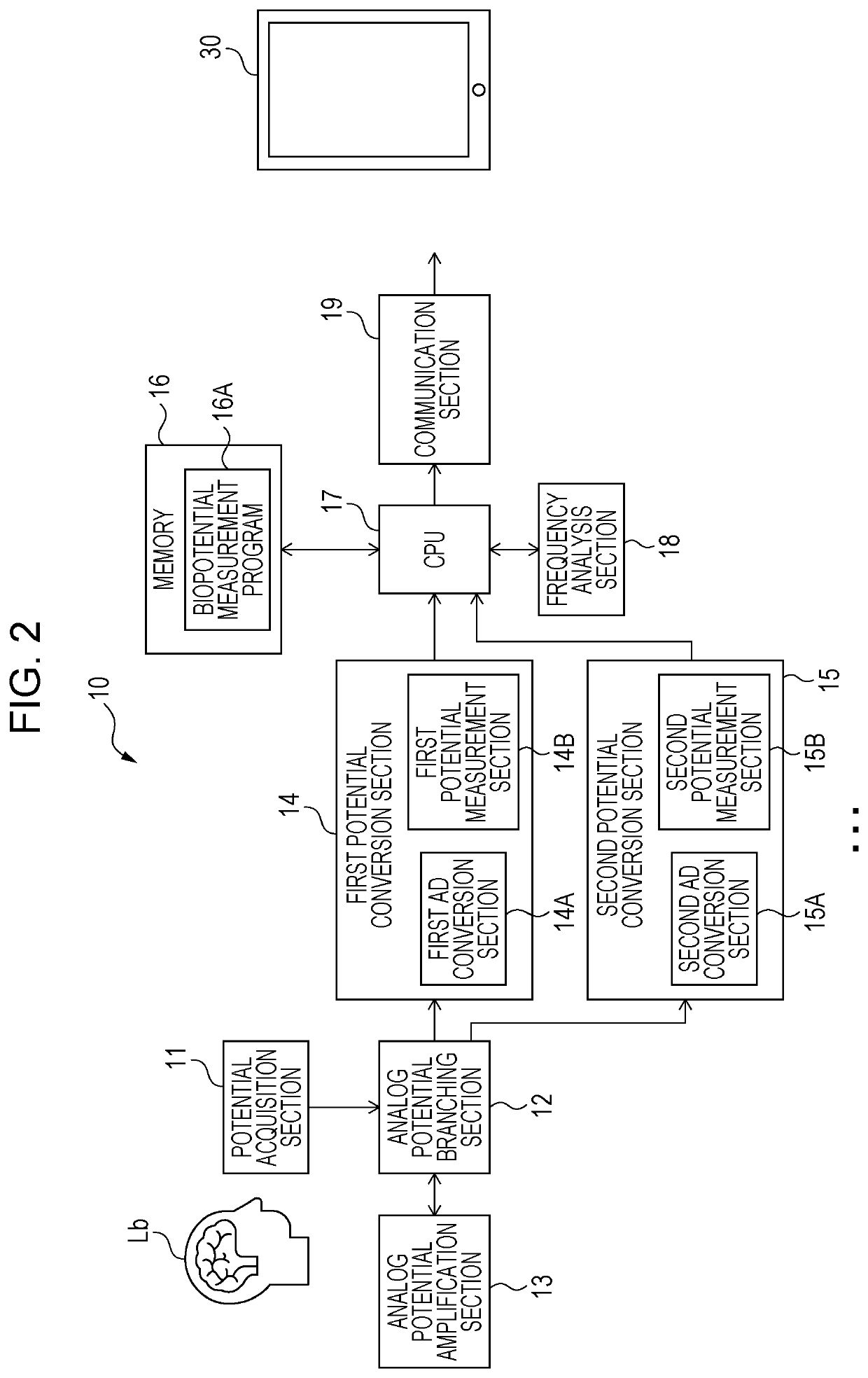
[0072]FIG. 7 is a block diagram illustrating an example of the electrical configuration of a biopotential measurement device 10A according to a second exemplary embodiment. Constituent elements that have substantially the same function as those of the biopotential measurement device 10 described in relation to the first exemplary embodiment are given the same reference numeral to omit repeated description.

[0073]As illustrated in FIG. 7, the biopotential measurement device 10A according to the present exemplary embodiment includes a potential acquisition section 20, an analog potential branching section 21, an analog potential amplification section 13, a first potential conversion section 14, a second potential conversion section 15, a ...

third exemplary embodiment

[0080]In the present exemplary embodiment, a case where an external device is operated in accordance with a measured brain wave potential using a brain computer interface function will be described. The term “brain computer interface function” as used herein refers to a function of operating an external device in accordance with a brain wave signal of a person to be measured.

[0081]FIG. 8 is a block diagram illustrating an example of the electrical configuration of a biopotential measurement device 10B according to a third exemplary embodiment. Constituent elements that have substantially the same function as those of the biopotential measurement device 10 described in relation to the first exemplary embodiment are given the same reference numeral to omit repeated description.

[0082]As illustrated in FIG. 8, the biopotential measurement device 10B according to the present exemplary embodiment includes a potential acquisition section 11, an analog potential branching section 12, an ana...


PUM


Abstract

A biopotential measurement device includes: a branching section that branches a biopotential into plural analog potentials; a first conversion section that converts one of the analog potentials branched by the branching section into a digital potential on the basis of a designated first conversion condition; and a second conversion section that converts the other of the analog potentials branched by the branching section into a digital potential on the basis of a second conversion condition. The amount of data obtained after a conversion with the second conversion condition is smaller than the amount of data obtained after a conversion with the first conversion condition.

Description

CROSS-REFERENCE TO RELATED APPLICATIONS[0001]This application is based on and claims priority under 35 USC 119 from Japanese Patent Application No. 2019-234480 filed Dec. 25, 2019.BACKGROUND(i) Technical Field[0002]The present disclosure relates to a biopotential measurement device and a non-transitory computer readable medium.(ii) Related Art[0003]Japanese Unexamined Patent Application Publication No. 2001-61800, for example, describes a brain wave signal processing device that analyzes time-series data on a brain wave detected by a brain wave detection device to reconfigure a brain wave signal from which a noise component due to a predetermined biological phenomenon has been removed. The brain wave signal processing device includes a decomposition unit that performs a wavelet decomposition of the time-series data on the brain wave to a predetermined decomposition level, and a reconfiguration unit that reconfigures a brain wave signal from which a noise component due to a predeterm...

Claims


Application Information

Patent Timeline
Patent Type & Authority Applications(United States)
IPC IPC(8): A61B5/00H03M1/12A61B5/0482
CPCA61B5/7225A61B5/0482A61B5/6803H03M1/12A61B5/374A61B5/7257A61B5/31A61B5/0006A61B5/313A61B5/308A61B5/375
Inventor KIMURA, TSUTOMU
Owner AGAMA X CO LTD
Why Eureka
Try Eureka