Apparatus and method for everting catheter for iud delivery and placement in the uterine cavity

a technology of uterine cavity and catheter, which is applied in the direction of balloon catheter, multi-lumen catheter, female contraceptives, etc., can solve the problems of uncontaminated or untouched balloon material being placed inside the vessel wall, pain for the patient, and traumatic pain, etc., to facilitate iud loading, enhance real-time visualization of iud placement, and increase ultrasound contrast. contrast, visibility and detection

Active Publication Date: 2021-07-01
CROSS BAY MEDICAL INC
View PDF1 Cites 3 Cited by
  • Summary
  • Abstract
  • Description
  • Claims
  • Application Information

AI Technical Summary

Benefits of technology

[0022]The everting balloon system can be used for the insertion of drug delivery devices, or insemination, and can seal the cervix for a duration of time for the deposition of drug agent or sperm and to allow for mobility for the patient. The everting balloon system can have a decoupling mechanism configured to decouple the outer catheter and inner catheter while maintaining hydraulic pressure in an everting balloon. The system can deflate and removal the everting balloon concurrently.
[0038]An IUD loading system can allow the user to load a separately supplied IUD into an everting catheter system. The loading system can include a cradle, split tube, and tray fixture to facilitate IUD loading into the everting catheter system.

Problems solved by technology

In some cases, the shear forces can result in trauma, pain for the patient, or perforation.
In addition, as the everting catheter deploys inside out, uncontaminated or untouched balloon material is placed inside the vessel wall.
This process can be particularly difficult in some nulliparous women who are seeking contraception with an IUD or women elect to use a hormonal IUD for alleviating abnormal bleeding.
A cervix could be difficult to traverse as a result of prior surgery, underlying stenosis, or other anatomical configuration or tortuosity that makes the passage of instruments or Hegar dilators difficult.
As mandrels or instruments get smaller in diameter, the likelihood of perforation or a false passage increases.
This in turn can lead to an uncomfortable procedure for the patient.
The stiffness of the cannula and the IUD implant itself also leads to patient discomfort during the placement procedure.
This vacuum effect can unintentionally remove the reproductive material from the uterine cavity in the situation of embryo transfer.

Method used


Image

  • Apparatus and method for everting catheter for iud delivery and placement in the uterine cavity
  • Apparatus and method for everting catheter for iud delivery and placement in the uterine cavity
  • Apparatus and method for everting catheter for iud delivery and placement in the uterine cavity

Examples


case 34

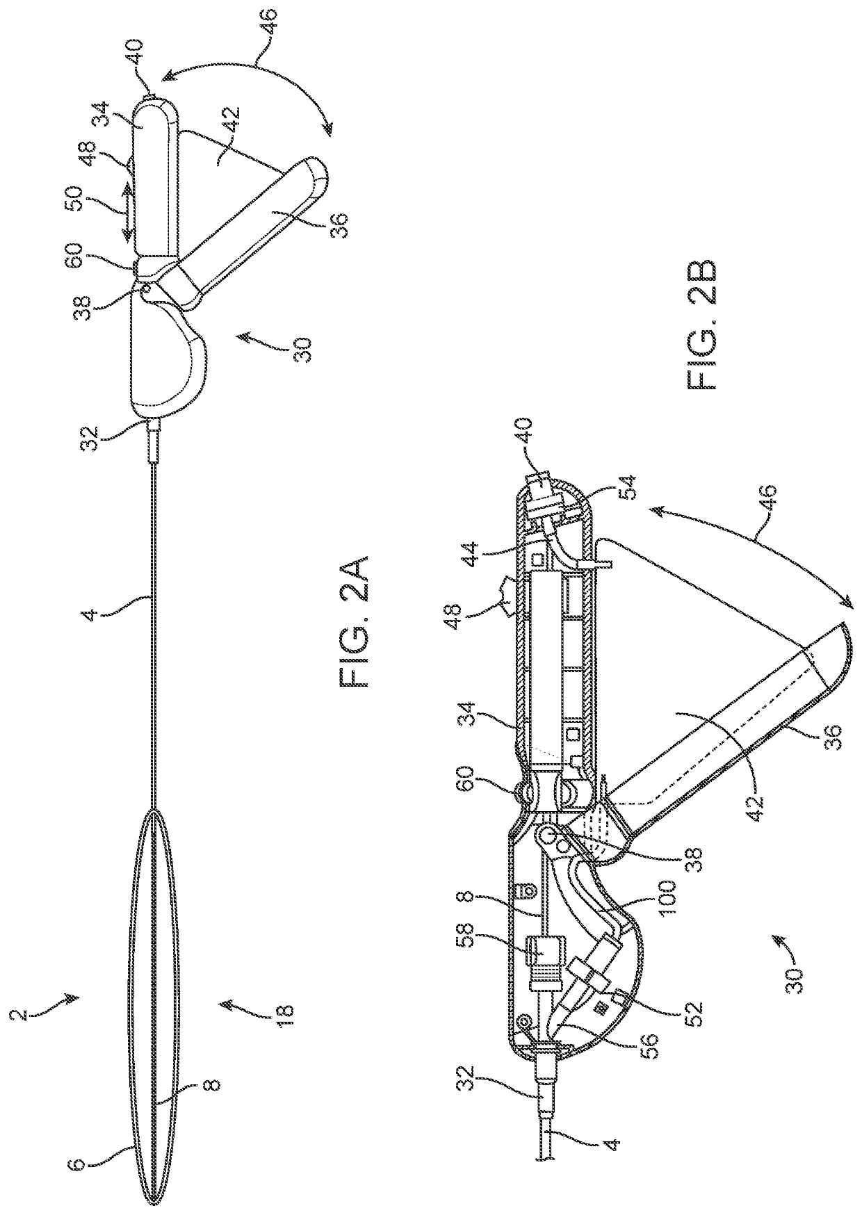
[0144]The system [[case]] handle case 34 can have a deflecting plate 92. The outer and / or inner catheters 4, 8 can press against the deflecting plate 92. The deflecting plate 92 can alter or deflect the path of the outer and inner catheters 4, 8 towards the longitudinally axial direction of the target site. The deflecting plate 92 can have a molded or formed groove, pins, plate, panel, or combinations thereof. The outer catheter 4 can be manufactured with a preset curve to accommodate the curved path within the system handle case 34.

[0145]The system handle case 34 can have a handle grip 96. The inner catheter 8 can have a linear inner catheter grip length 98. The inner catheter grip length 98 can be a length of the inner catheter 8 in the uneverted state in the handle grip 96. The inner catheter grip length 98 can be about 12 cm of inner catheter 8 in the uneverted state, for example corresponding to an eversion length for the inner catheter grip length 98 of about 6 cm (e.g., about...


PUM


Abstract

An everting balloon system is disclosed that can be used for the placement of an IUD within the uterine cavity of a female patient. The everting balloon system with IUD can be used to access a uterine cavity at specific locations in the fundus. A one-handed IUD delivery system for placement with an everting catheter is disclosed. An IUD loading system for placement within an everting catheter is disclosed. The everting catheter with an IUD can simplify the process of IUD placement within the uterine cavity.

Description

CROSS-REFERENCE TO RELATED APPLICATIONS[0001]This application is a divisional application of U.S. application Ser. No. 17 / 067,352, filed Oct. 9, 2020, which claims priority to U.S. Provisional Application No. 62 / 913,160, filed Oct. 9, 2019, both of which are incorporated by reference herein in their entireties.BACKGROUND[0002]The apparatuses and methods disclosed herein can have utility for everting catheters that are characterized with an inner catheter, outer catheter, and everting membrane that can be connected to both catheters. The inner catheter may contain an inner lumen to pass fluid or media, drugs or therapeutic agents, instruments or devices such as intrauterine uterine devices (IUDs), endoscopes, and other catheters.[0003]For physicians and medical professionals, accessing systems for vessels and bodily cavities in patients have typically used various guidewire and catheter technologies. In some cases, the process requires the insertion of a series of mandrels or wires t...

Claims


Application Information

Patent Timeline
Patent Type & Authority Applications(United States)
IPC IPC(8): A61F6/18A61M25/01A61M25/00
CPCA61F6/18A61M25/0119A61M25/0075A61M2025/0031A61M2025/0034A61M2210/1425A61M25/003A61F6/146A61M25/1006A61M2025/1065A61M2025/1068
Inventor BACICH, STEVEN R.YUREK, MATTHEW THOMASGREELIS, JACKVIDYARTHI, PIUSH
Owner CROSS BAY MEDICAL INC
Why Eureka
Try Eureka