

Resonator, oscillator, and quantum computer
- Summary
- Abstract
- Description
- Claims
- Application Information
AI Technical Summary
Benefits of technology
Problems solved by technology
Method used
Image

Examples
first example embodiment
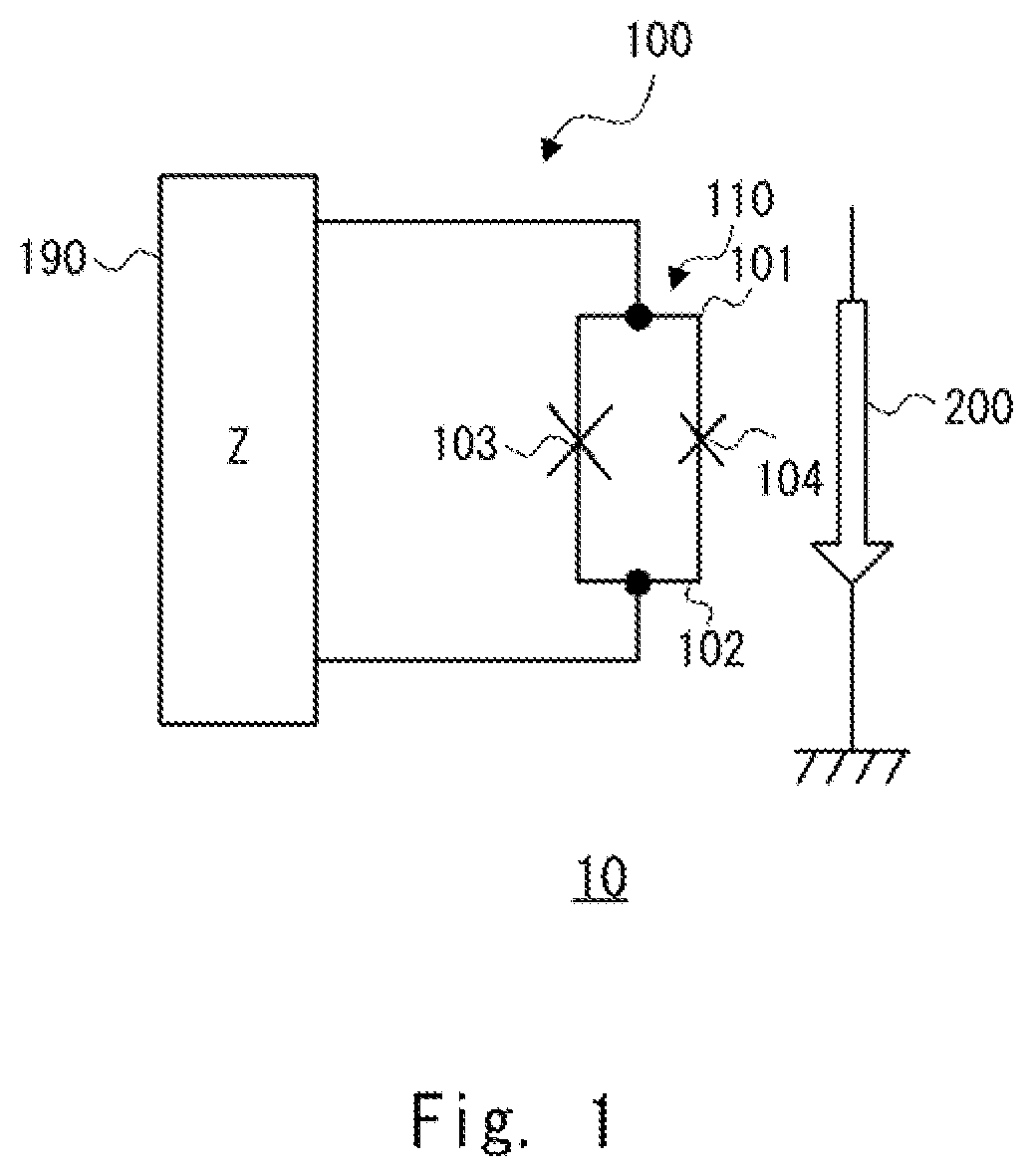
[0025]FIG. 1 is a schematic diagram showing an example of an oscillator 10 which is a Josephson parametric oscillator according to a first example embodiment. Hereinafter, the Josephson parametric oscillator is also referred to simply as an oscillator. As shown in FIG. 1, the oscillator 10 includes a resonator 100 and a magnetic field generation unit 200. The resonator 100 includes a loop circuit 110 and an impedance circuit 190 connected to the loop circuit 110. Note that the impedance circuit 190 is an arbitrary circuit that forms, by being connected to the loop circuit 110, a resonator for generating a parametric oscillation. As will be described later, the resonant frequency of the resonator 100 is set (i.e., determined) by a magnetic field applied to the loop circuit 110.
[0026]The loop circuit 110 includes a first superconducting line 101 that connects a first Josephson junction 103 and a second Josephson junction 104, and a second superconducting line 102 that connects the fir...
second example embodiment
[0038]As a second example embodiment, a distributed constant-type Josephson parametric oscillator will be described. FIGS. 6 and 7 are schematic diagrams showing examples of the configuration of an oscillation apparatus including a distributed constant-type Josephson parametric oscillator. An oscillation apparatus 1 shown in FIG. 6 includes an oscillator 11 which is a distributed constant-type Josephson parametric oscillator, a current control unit 50, a readout unit 51, and an input / output capacitor 52. Similarly, an oscillation apparatus 2 shown in FIG. 7 includes an oscillator 12 which is a distributed constant-type Josephson parametric oscillator, a current control unit 50, a readout unit 51, and an input / output capacitor 52.
[0039]The oscillator 11 (see FIG. 6) includes a resonator 300 and the above-described magnetic field generation unit 200. The magnetic field generation unit 200 and the resonator 300 are magnetically coupled with each other through mutual inductance. In othe...
third example embodiment
[0043]As a third example embodiment, a lumped constant-type Josephson parametric oscillator will be described. The distributed constant-type Josephson parametric oscillator is not suitable for the integration because the occupied area of the resonator is too large. In contrast to this, since the lumped constant-type Josephson parametric oscillator does not require a waveguide, it can be formed in a smaller size than that of the distributed constant-type Josephson parametric oscillator.
[0044]FIG. 8 is a schematic diagram showing an example of a configuration of an oscillation apparatus including a lumped constant-type Josephson parametric oscillator. An oscillation apparatus 3 shown in FIG. 8 is different from that shown in FIG. 6 or FIG. 7 because the distributed constant-type oscillator is replaced by a lumped constant-type oscillator 13. That is, the oscillation apparatus 3 includes an oscillator 13 which is a lumped constant-type Josephson parametric oscillator, a current control...
PUM
 Abstract
Description
Claims
Application Information