
Heating coil, heating apparatus and manufacturing method of workpiece

Pending Publication Date: 2021-07-01
NETUREN CO LTD
View PDF0 Cites 0 Cited by
  • Summary
  • Abstract
  • Description
  • Claims
  • Application Information

AI Technical Summary

Benefits of technology

The invention is about a heating coil that can prevent the outer edge of a hole in a workpiece from getting too hot and improve productivity. This means that the heating coil is designed to heat the workpiece evenly and efficiently, which can save time and reduce waste.

Problems solved by technology

Heating methods described in JP2001-152242A and JP2001-192734A require a large number of plugs for the induction heating of a large amount of workpieces and require a large number of man-hours to insert the plugs into the holes in the peripheral surface of the workpiece, which may lead to a decrease in productivity.

Method used


Image

  • Heating coil, heating apparatus and manufacturing method of workpiece
  • Heating coil, heating apparatus and manufacturing method of workpiece
  • Heating coil, heating apparatus and manufacturing method of workpiece

Examples


Embodiment Construction

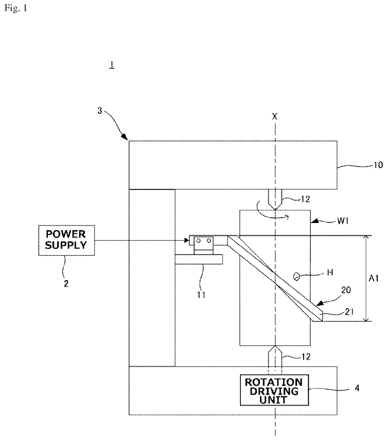
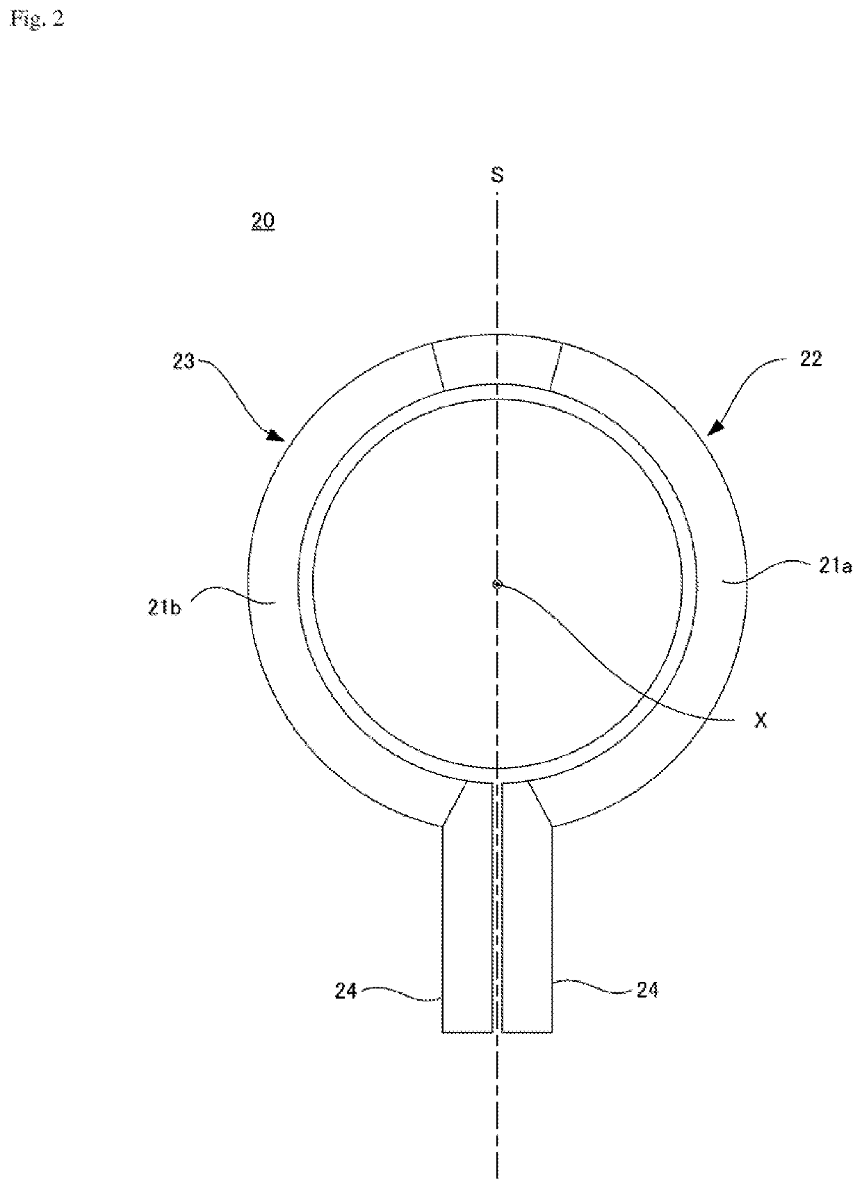
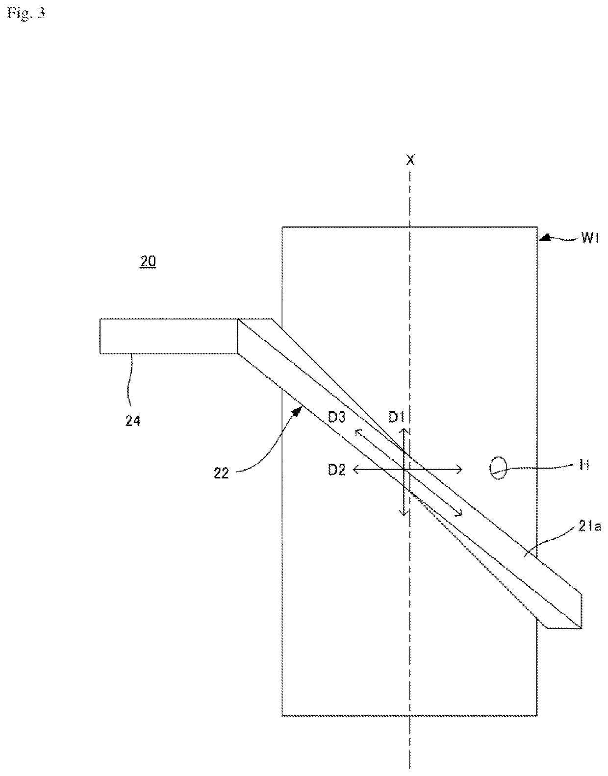
[0025]FIG. 1 schematically illustrates an example of a heating coil and a heating apparatus for illustrating an embodiment. FIGS. 2 to 4 illustrate the heating coil in FIG. 1.

[0026]A heating apparatus 1 is a stationary heating apparatus that is configured to inductively heat an outer peripheral surface of a cylindrical workpiece W1. A hole H extending in a radial direction from the outer peripheral surface is formed in the workpiece W1. The hole H may be a through hole or a blind hole.

[0027]The heating apparatus 1 includes a heating coil 20 that is configured to inductively heat the outer peripheral surface of the workpiece W1, a power supply 2 that is configured to supply high frequency AC power to the heating coil 20, a supporting portion 3 that is configured to support the workpiece W1 and the heating coil 20, and a rotation driving unit 4 that is configured to rotate the workpiece W1 about a central axis X of the workpiece W1.

[0028]The heating coil 20 is configured such that a c...


PUM


Abstract

A heating coil is configured to induction heat a workpiece having a hole. The heating coil includes first and second heating units respectively having conductors. The conductors of the first and second heating units extend in inclination directions intersecting an axial direction and a circumferential direction of an outer peripheral surface of the workpiece.

Description

TECHNICAL FIELD[0001]The present invention relates to a heating coil and a heating apparatus used for induction heating of an outer peripheral surface of a workpiece having a cylindrical peripheral surface and having a hole extending in a central direction from the peripheral surface.BACKGROUND ART[0002]A return hole extending in a center direction is formed on an inner peripheral surface of a ball nut. When induction heating is applied to the inner peripheral surface of the ball nut in a state where the return hole is opened, an induced current flowing in a circumferential direction on a surface layer of the inner peripheral surface may be concentrated at edge portions of both sides of a periphery of the return hole that are opposed to each other in an axial direction of the inner peripheral surface, so that the edge portion where the induced current is concentrated may be overheated and melted. According to methods disclosed in JP2001-152242A and JP2001-192734A, induction heating ...

Claims


Application Information

Patent Timeline
IPC IPC(8): H05B6/36H05B6/10
CPCH05B6/36H05B6/102Y02P10/25
Inventor HOSOGI, MAHOTANAKA, YOSHIMASAIWASAKI, SYOICHIROKOSAKI, HIDEYUKIKODAMA, YUUJI
Owner NETUREN CO LTD
Learn More