Pipette tip rack system

a tip rack and pipette technology, applied in the field of pipette tip racks, to achieve the effect of convenient access, convenient cover of remaining tips, and convenient one-touch operation

Pending Publication Date: 2021-07-08
INTEGRA BIOSCI CORP
View PDF4 Cites 4 Cited by
  • Summary
  • Abstract
  • Description
  • Claims
  • Application Information

AI Technical Summary

Benefits of technology

[0008]As mentioned, the tip dispenser facilitates reliable one-touch operation by securing the thermoformed tip container and tip deck reliably within the base. The base may be weighted to provide additional stability. In addition, a dampening mechanism can be used to dampen the speed at which the dispenser cover opens. Before use, the clamshell tip container loaded with pipette tips is set in the base, and a locking tab on the lid of thermoformed clamshell container is released to allow the lid to open. In one embodiment, the front wall of the lid has one or more detents that engage with the backside of one or more detents on the locking tab to hold the locking tab against the front wall of the clamshell lid. Holding the locking tab against the lid stows it out of the way of the latch on the dispenser. Alternatively, the locking tab can be manually stowed between the front wall of the clamshell lid and the front wall of the dispenser cover by tucking the locking tab under the cover of the dispenser when loading the tip container. Then, the cover of the tip dispenser is closed and latched shut. It is preferred that the cover of the dispenser be made of a clear material, and as mentioned above that the clamshell tip container be made of a clear material, so that the user can see the pipette tips and the tip deck when the cover is closed. When the laboratory worker needs to access the pipette tips, the latch is released preferably by pushing a button on the front of the dispenser base and the lifting mechanism automatically lifts the dispenser cover and at the same time the lid of the clamshell tip container to expose pipette tips held in the tip deck. The laboratory worker then mounts one or more pipette tips onto the pipette and closes the dispenser cover and clamshell lid in order to reduce the risk of contamination. The lab worker is able to open and close the dispenser cover, as mentioned, conveniently even with both hands full.
[0012]In one exemplary embodiment of the invention, the thermoformed clamshell tip container sits with the bottom of the receptacle on the floor of the dispenser, such that vertical support for the tip deck is normally provided by the walls of the thermoformed container. This configuration enables more tolerance for the lifting arms on the dispenser below the respective overhanging wings on the thermoformed container to facilitate reliable operation. It is desired that the walls of the of the dispenser base have support stanchions on the inside to provide lateral support to the sidewalls of the lower receptacle of the thermoformed clamshell.
[0013]Another aspect of the clamshell container addresses the need to have a reliable locking mechanism. The rims of the receptacle and the lid do not have an interference fit as is common with other thermoformed containers because the dispenser needs to open and close the lid repeatedly. Accordingly, a hinged locking tab is used to latch the lid closed to the front wall of the lower receptacle of the clamshell container. In one embodiment of the invention, the clamshell container uses a particularly reliable latching mechanism. The latching mechanism includes a formed catch detent on the front sidewall of the lower receptacle. The catch detent has a base wall and sidewalls extending outward from the base wall. Each sidewall has a proximal portion adjacent the base wall and a distal portion. The distance between the respective distal portions is less than the distance between the respective proximal sections to form interference for the operation of the catch. A hinged locking tab is provided along a lower edge of the front wall of the lid. The locking tab has a formed engagement protrusion that engages with the formed catch detent on a front wall of the lower receptacle in order to releasably close the lid. The formed engagement protrusion includes a pair of latch bosses, each extending laterally from one side of the engagement protrusion. The distance between the respective distal portions of the sidewalls of the catch detent is less than the full span between the latch bosses; however, the latch bosses reside between the respective proximal portions of the sidewalls of the catch detent when the locking tab is in a closed position. When the locking tab is pushed closed, the engagement protrusion and the laterally extending latch bosses on the locking tab press through the opening between the distal portions of the catch detent on the lower receptacle. The distal portions of the catch detent, on the other hand, hold the engagement protrusion, the laterally extending latch bosses and the entire locking tab in place when the locking tab is closed. Having the latching interference along the sidewalls of the catch detent and the engagement protrusion of the locking tab enables a robust latching operation even if there is vertical offset due to imperfections in the operation of thermoformed hinges or otherwise. To open the locking mechanism, the locking tab is pulled to pull the engagement protrusion and the respective latch bosses past the distal portions of the catch detent. Desirably, the proximal wall is configured to provide space for movement of the locking tab when it is in the closed position. This makes it easier for the user to grab the locking tab in order pull on it to open the latch.
[0014]Another desirable feature is to configure both the tip container and the dispenser so that the pipette tip collars are presented at a level higher than the upper rim of the dispenser base and the upper rim of the clamshell receptacle. This enables the laboratory worker to mount tips using a multi-channel pipette with some of the channels overhanging the rim of the base.
[0015]The pipette tip rack system as described above enables the laboratory worker to repeatedly access pipette tips in the dispenser and cover the tips in the dispenser after one or more tips have been mounted to the pipette while the lab worker is pipetting reagents or samples. The system is configured primarily, as mentioned, to facilitate reliable one-touch operation so that the laboratory worker is able to keep the pipette in hand throughout the entire tip mounting process. As mentioned, a laboratory worker can even operate the dispenser with both hands otherwise occupied, e.g., activating the cover release and closing the dispenser cover with the back of a hand.

Problems solved by technology

When not using the tip dispenser, however, it is likely the laboratory worker will need to hold the thermoformed container with one hand to stabilize the container while using the other hand to hold the pipette and mount the tip or tips.

Method used


Image

  • Pipette tip rack system
  • Pipette tip rack system
  • Pipette tip rack system

Examples


Embodiment Construction

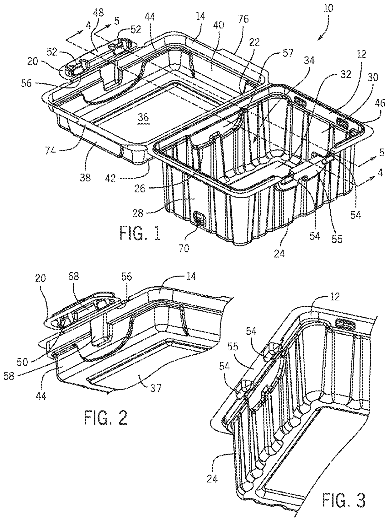
[0061]FIG. 1 illustrates a thermoformed clamshell tip container 10 that is constructed in accordance with an exemplary embodiment of the invention. The tip container 10 includes a lower receptacle 12 and an upper lid 14, which are connected together with a hinge 22. The lower receptacle 12 includes a front wall 24, a rear wall 26, lateral side walls 28, 30 and a bottom wall 32. The bottom wall 32, the lateral side walls 28, 30 and the front 24 and rear 26 walls define a well 34 for storing pipette tips. The bottom wall 32 has a raised flat, rectangular portion 33 surrounded by an outer portion 35 that supports the container 10 when it sits on a flat surface. The raised or recessed flat portion 33 fits over a raised rectangular portion 37 (FIG. 2) of the lid to facilitate stable multi-container stacking. The lateral side walls 28 and 30, and the front wall 24 and the rear wall 26 include strengthening ribs. The lid 14 on the clamshell tip container 10 includes a top wall 36, lateral ...


PUM


Abstract

A pipette tip rack system includes a thermoformed clamshell tip container and a dispenser for the clamshell tip container. The tip dispenser includes a base for holding the clamshell container, cover and a lifting mechanism for lifting the lid of the tip container and the cover when a latch on the base is released. The tip dispenser is configured to facilitate one-touch operation so that a laboratory work may hold a pipette in the other hand while using the dispenser, and conveniently open and close the dispenser cover to reduce the risk of contamination. The dispenser can be used without the thermoformed tip container as well.

Description

FIELD OF THE INVENTION[0001]The invention relates to pipette tip racks, and more particularly to environmentally friendly, disposable tip containers that are used with a dispenser to store the container and the tips on the laboratory benchtop. Both the dispenser and the tip container are configured in particular to enable convenient one-touch operation. The user can use the dispenser once it is loaded with pipette tips even if items occupy both hands yet do so without the threat of contamination.BACKGROUND OF THE INVENTION[0002]Pipette tip racks are used to organize disposable pipette tips in a manner that is convenient to mount the tips onto a pipette. The racks typically include a tip deck or plastic insert with an array of holes, such as an 8×12 array, through which the pipette tips hang with the tip collars exposed upward. Conventional racks comprise a substantially rigid box suspending the tip deck at a height sufficient for the pipette tips to pass through the holes and be sus...

Claims


Application Information

Patent Timeline
Patent Type & Authority Applications(United States)
IPC IPC(8): B01L9/00B01L3/02B65D43/16
CPCB01L9/543B01L3/0275B65D2543/00194B01L2300/043B65D2543/00296B65D43/162B01L2200/087B01L2200/022B01L2300/0858B01L2300/12B01L2400/0403
Inventor BONNOITT, JR., GEORGE K.LACROIX, CHRISTOPHER
Owner INTEGRA BIOSCI CORP
Why Eureka
Try Eureka