Electric heating mat

a heating mat and electric technology, applied in the field of electric heating mats, can solve the problems of residual current flow, small quantity of permanent consumption of energy, multi-pressure sensors to be implemented, etc., and achieve the effect of reducing heat energy

Pending Publication Date: 2021-07-08
THURINGISCHES INST FUR TEXTIL & KUNST FORSCHUNG EV RUDOLSTADT
View PDF4 Cites 1 Cited by
  • Summary
  • Abstract
  • Description
  • Claims
  • Application Information

AI Technical Summary

Benefits of technology

[0019]To prevent the flow of current in the unloaded state, electrically non-conductive spacers (4) must be attached with a certain, i.e. defined, spacing from one another at points or in a linear arrangement between the electrodes (2), (3) and the electrically conductive plastic (1) of the heating body, preventing the electrodes (2),(3) from coming into limited, random, local contact with the electrically conductive plastic (1) of the heating body. The magnitude of the current is reduced entirely to zero through the application, according to the invention, of the spacers (4) in the absence of applied pressure. The spacers (4) can be thin, flexible, foam foils or thin textile fibers. It is necessary to ensure here that the surface covered by the spacers (4) is very small, if possible less than 10%, in comparison with the total surface of the heating mat or electrically conductive plastic (1) heating body total area.

Problems solved by technology

A disadvantage of this invention is that multiple pressure sensors must be implemented, depending on the desired local resolution.
This disadvantage is overcome in the patent document JPH09245937 in that the electrically conductive heating layer is itself implemented in a pressure-sensitive manner, so that electrical heating is only generated at locations where a force or pressure acts.
A disadvantage of this solution is, however, that a residual current flows even in the absence of a load due to the finite resistance that is still present, as a result of which a small quantity of energy is permanently consumed.

Method used


Image

  • Electric heating mat
  • Electric heating mat

Examples


example 1

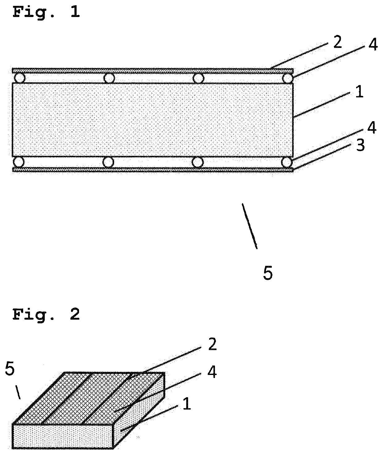
[0023]This example shows the principle of operation of the invention. A conductive PE foam (ELS-M) with dimensions of 470×320 mm and a thickness of 6 mm has gauze electrodes of stainless steel applied to both sides. The gauze electrodes consist of stainless steel wires with a mesh width of 1.4 mm, and are fastened loosely to the foam at the edge. PET plastic filaments with a diameter of 0.5 mm spaced about 6 cm apart are woven into the wire mesh as spacers between the lower gauze electrode and the conductive foam. 28 Foam platelets (2 mm thick) are glued about 8 cm apart from one another as spacers between the upper gauze electrode and the conductive foam. In principle, other materials and body shapes can be used as spacers, provided they do not prevent the wide-area contact between the electrodes and the conductive foam when loaded.

[0024]If a voltage of 60 V is applied to the electrodes, no measurable current flows through the heating mat in the unloaded case. If the mat is locally...


PUM

PropertyMeasurementUnit
electrical conductivityaaaaaaaaaa

Abstract

The invention relates to an electric surface heater, or heating mat, based on an electrically conductive polymer foil or a conductive polymer foam that only heats locally where persons, animals or objects are positioned on the mat. Energy can thereby be saved in comparison with a full-area heater. Ideally, this local heat generation functions without any external electronic control or regulation.

Description

CROSS-REFERENCE TO RELATED APPLICATIONS[0001]This application claims priority to German Patent Application 10 2020 100 226.2 filed Jan. 8, 2020, which is hereby in-corporated herein by reference in its entirety.FIELD OF THE INVENTION[0002]The invention relates to an electric surface heater or heating mat based on an electrically conductive polymer foil or a conductive polymer foam that only heats locally where persons, animals or objects are positioned on the mat. Energy can thereby be saved in comparison with a full-area heater. Ideally, this local heat generation functions without any external electronic control or regulation.BACKGROUND OF THE INVENTION[0003]Electric surface heaters have many applications, inter alia as wall heaters, floor heaters, mirror heaters, terrarium heaters, waterbed heaters, heatable foot mats and many more others. Whereas, for example, a large-area heat output is desired for heating rooms, in the case of heatable foot mats or heated blankets for domestic...

Claims


Application Information

Patent Timeline
Patent Type & Authority Applications(United States)
IPC IPC(8): F24D13/02H05B3/14H05B3/03H05B3/34H05B1/02
CPCF24D13/022H05B3/146H05B3/03H05B3/34H05B2203/01H05B2203/016H05B2214/04H05B2203/02H05B1/0202H05B3/02H05B2203/026H05B2203/013H05B3/267H05B3/14H05B2203/029
Inventor SCHRÖDNER, MARIOSCHACHE, HANNESSZABÓ, LAJOSEHRHARDT, MARCEL
Owner THURINGISCHES INST FUR TEXTIL & KUNST FORSCHUNG EV RUDOLSTADT
Why Eureka
Try Eureka