

A heavy-duty jack stand
- Summary
- Abstract
- Description
- Claims
- Application Information
AI Technical Summary
Benefits of technology
Problems solved by technology
Method used
Image

Examples
Embodiment Construction
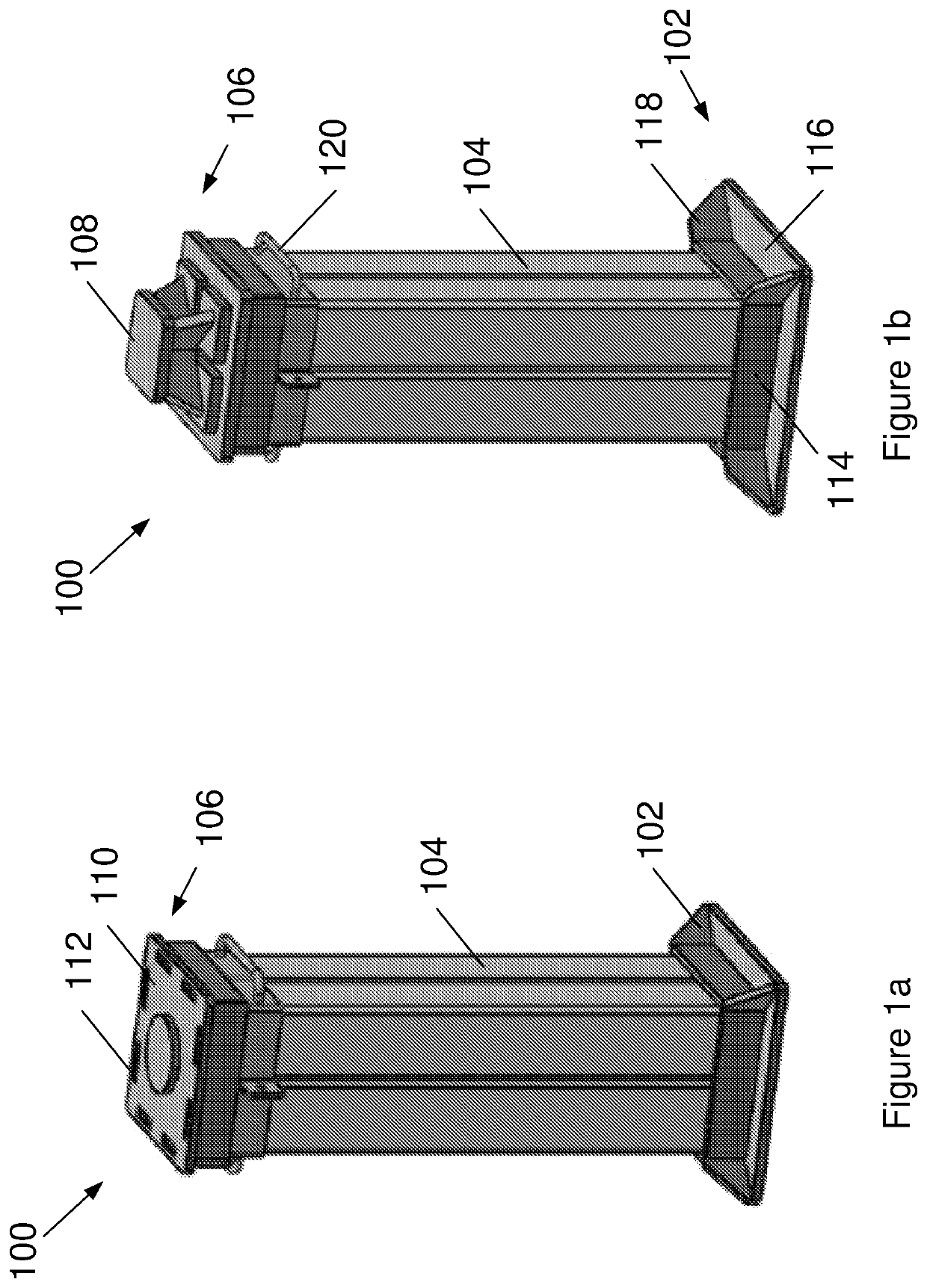
[0038]According to one aspect of the present invention, there is provided a heavy-duty jack stand 100 shown in FIG. 1, rated to support payloads over 30 tonne and up to 400 tonne. The jack stand 100 is also lightweight, typically weighing between about 30 kg and 70 kg depending upon rating, and thereby being about 50%-70% lighter than conventional stands.
[0039]The construction of the jack stand 100 shown in FIG. 1a is similar to that of PCT / AU2017 / 050349, which is incorporated herein by reference. The jack stand 100 includes a square base 102, and a light-weight composite-material post 104 for extending from the base 102. A top 106 is provided for topping the post 104 and engaging with a load (e.g. truck) supported by the jack stand 100.
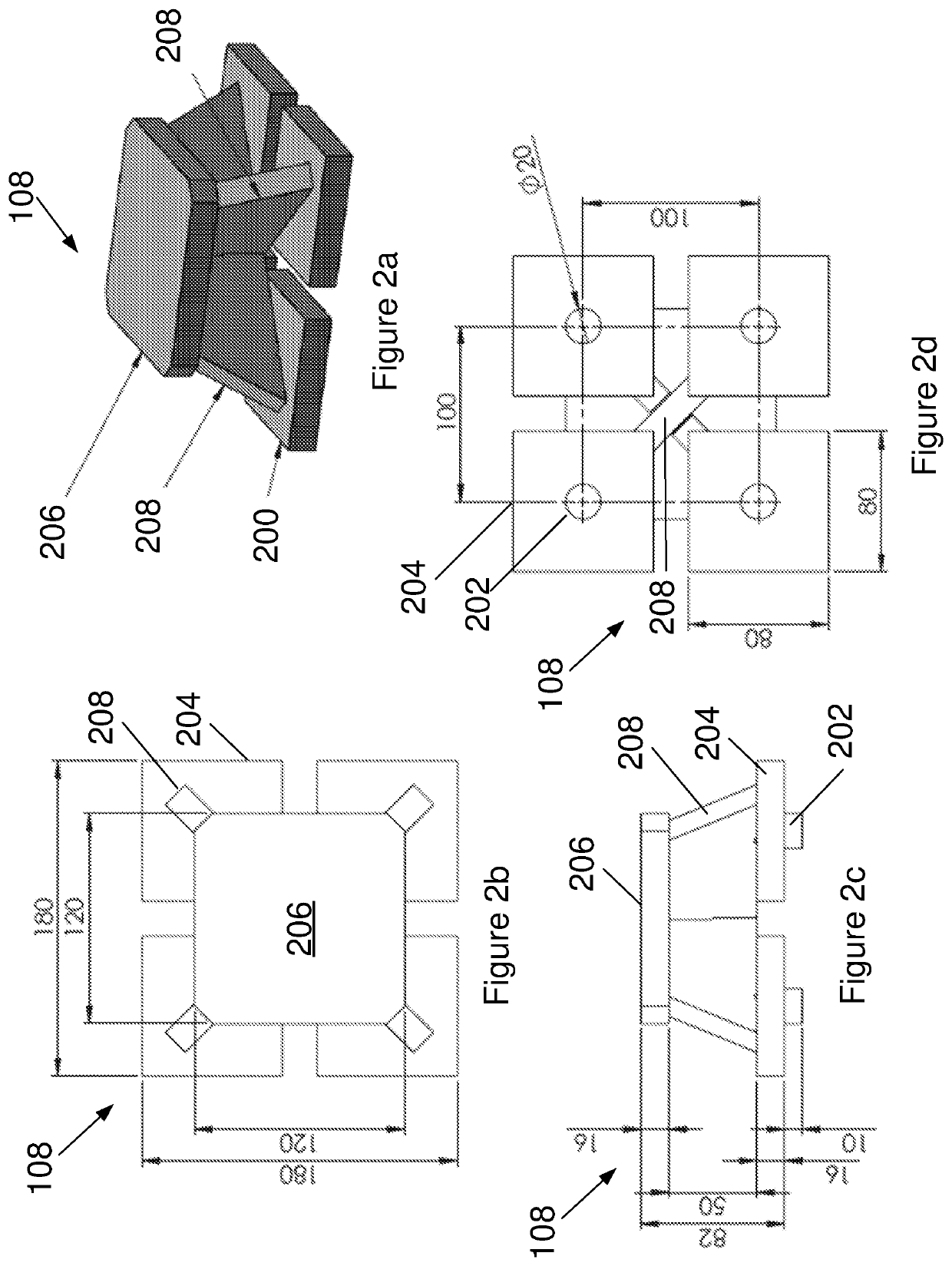
[0040]As can best be seen in FIG. 1b, the top 106 includes a load spreader 108 for spreading the weight of the load to the post 104. Advantageously, the spreader 108 spreads the weight of the load to the post thereby resulting in a more heavy-duty ja...
PUM
 Abstract
Description
Claims
Application Information