Optical Image Capturing Module

a technology of optical image and module, applied in the field of optical image capturing system, can solve the problems of deterioration of quality in peripheral image formation, difficulty in manufacturing, distortion rate in image formation, etc., and achieve the effect of reducing the height of the optical system, and improving image quality

Inactive Publication Date: 2021-07-22
ABILITY OPTO ELECTRONICS TECH
View PDF69 Cites 0 Cited by
  • Summary
  • Abstract
  • Description
  • Claims
  • Application Information

AI Technical Summary

Benefits of technology

[0040]The optical image capturing system described above is applicable to the demand of video recording with above millions or ten millions-pixels (e.g. 4K2K or the so-called UHD and QHD) and leads to a good imaging quality.
[0041]The height of optical system (HOS) may be reduced to achieve the minimization of the optical image capturing system when the absolute value of f1 is larger than f4 (|f1|>|f4|).
[0042]When |f2|+|f3|>f1|+|f4|, at least one lens among the second lens to the third lens may have a weak positive refractive power or a weak negative refractive power. The weak refractive power indicates that an absolute value of the focal length of a specific lens is greater than 10. When at least one lens among the second lens to the third lens has the weak positive refractive power, the positive refractive power of the first lens can be shared by this configuration, such that the unnecessary aberration will not appear too early. On the contrary, when at least one lens among the second lens to the third lens has the weak negative refractive power, the aberration of the optical image capturing system can be slightly corrected.
[0043]Besides, the fourth lens may have negative refractive power, and the image side thereof may be a concave surface. Hereby, this configuration is beneficial to shorten the back focal length of the optical image capturing system so as to keep the optical image capturing system minimized. Moreover, at least one surface of the fourth lens may possess at least one inflection point, which is capable of effectively reducing the incident angle of the off-axis rays, thereby further correcting the off-axis aberration.

Problems solved by technology

But the optical image capturing system with the large aperture design often produces more aberration resulting in the deterioration of quality in peripheral image formation and difficulties of manufacturing, and the optical image capturing system with wide angle of view design increases distortion rate in image formation, thus the optical image capturing system in prior arts cannot meet the requirement of the higher order camera lens module.
Therefore, how to design an optical image capturing system capable of balancing the requirement for higher total pixel count and quality of the formed image as well as the minimization of camera module by effectively increasing the amount of admitted light and the angle of view the optical image capturing system has become a pressing issue.

Method used


Image

  • Optical Image Capturing Module
  • Optical Image Capturing Module
  • Optical Image Capturing Module

Examples


first embodiment

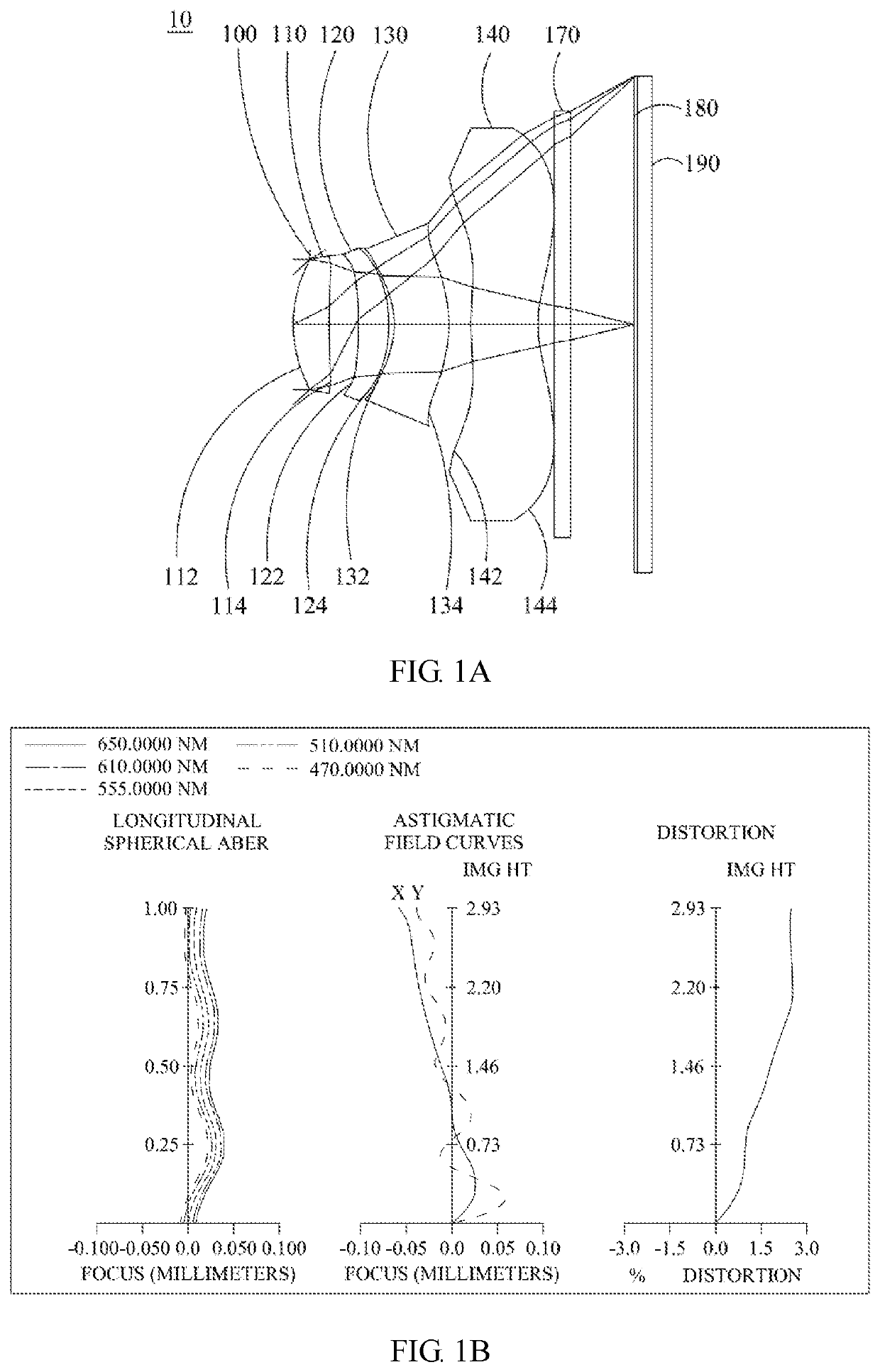
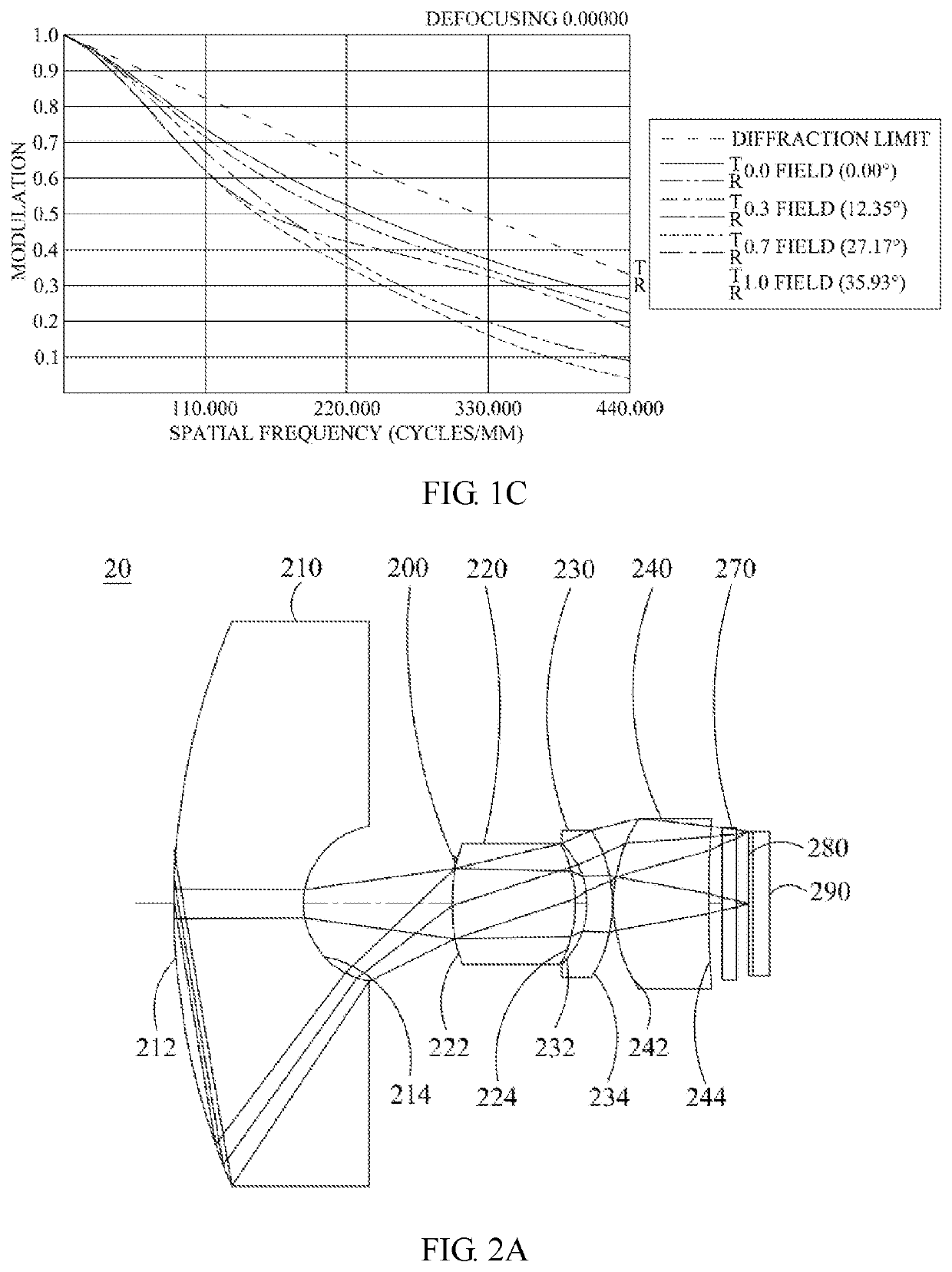
[0102]Please refer to FIGS. 1A to 1C. FIG. 1A is a schematic view of the optical image capturing system according to the first embodiment of the present invention. FIG. 1B is a curve diagram illustrating the spherical aberration, astigmatism and optical distortion of the optical image capturing system in order from left to right according to the first embodiment of the present invention. FIG. 1C is a characteristic diagram of modulation transfer of visible light spectrum for the optical image capturing system according to the first embodiment of the present invention. As shown in FIG. 1A, an optical image capturing system includes, in the order from the object side to the image side, an aperture 100, a first lens 110, a second lens 120, a third lens 130, a fourth lens 140, an IR-cut filter 170, an image plane 180, and an image sensor element 190.

[0103]The first lens has positive refractive power and is made of plastic. The object side 112 of the first lens is a convex surface and th...

second embodiment

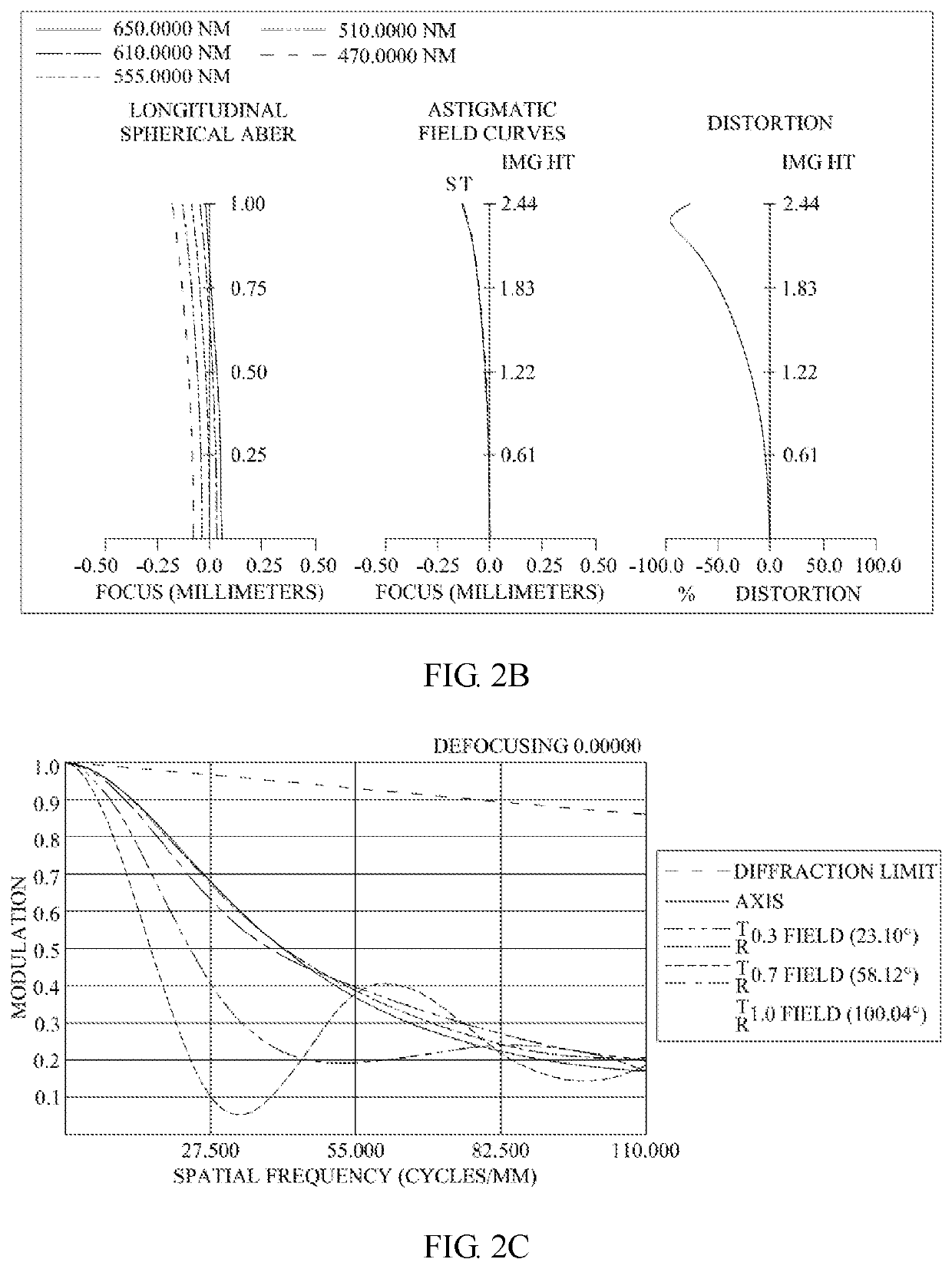
[0150]Please refer to FIGS. 2A to 2C. FIG. 2A is a schematic view of the optical image capturing system according to the second embodiment of the present invention. FIG. 2B is a curve diagram illustrating the spherical aberration, astigmatism and optical distortion of the optical image capturing system in order from left to right according to the second embodiment of the present invention. FIG. 2C is a characteristic diagram of modulation transfer of visible light spectrum for the optical image capturing system according to the second embodiment of the present invention. As shown in FIG. 2A, an optical image capturing system includes, in the order from the object side to the image side, a first lens 210, an aperture 200, a second lens 220, a third lens 230, a fourth lens 240, an IR-cut filter 270, an image plane 280, and an image sensor element 290.

[0151]The first lens 210 has negative refractive power and is made of glass. The object side 212 of the first lens 210 is a convex surfa...

third embodiment

[0161]Please refer to FIGS. 3A to 3C. FIG. 3A is a schematic view of the optical image capturing system according to the third embodiment of the present invention. FIG. 3B is a curve diagram illustrating the spherical aberration, astigmatism and optical distortion of the optical image capturing system in order from left to right according to the third embodiment of the present invention. FIG. 3C is a characteristic diagram of modulation transfer of visible light spectrum for the optical image capturing system according to the third embodiment of the present invention. As shown in FIG. 3A, an optical image capturing system includes, in the order from the object side to the image side, a first lens 310, an aperture 300, a second lens 320, a third lens 330, a fourth lens 340, an IR-cut filter 370, an image plane 380, and an image sensor element 390.

[0162]The first lens 310 has negative refractive power and is made of glass. The object side 312 of the first lens 310 is a convex surface ...


PUM


Abstract

A four-piece optical image capturing system is disclosed. In order from an object side to an image side, the optical image capturing system along the optical axis includes a first lens with positive refractive power; a second lens with refractive power; a third lens with refractive power; and a fourth lens with refractive power; and at least one of the image-side surface and object-side surface of each of the four lenses are aspheric. The optical image capturing system can increase aperture value and improve the imagining quality for use in compact cameras.

Description

CROSS-REFERENCE TO RELATED APPLICATION[0001]This application claims priority from Taiwan Patent Application No. 109101719, filed on Jan. 17, 2020, in the Taiwan Intellectual Property Office, the content of which is hereby incorporated by reference in its entirety for all purposes.BACKGROUND OF THE INVENTION1. Field of the Invention[0002]The present invention relates to an optical image capturing system, and more particularly to a compact optical image capturing system which can be applied to electronic products.2. Description of the Related Art[0003]In recent years, with the rise of portable electronic devices having camera functionalities, the demand for an optical image capturing system has gradually been raised. The image sensing device of the ordinary photographing camera is commonly selected from a charge coupled device (CCD) or a complementary metal-oxide semiconductor sensor (CMOS Sensor). Also, as advanced semiconductor manufacturing technology enables the minimization of th...

Claims


Application Information

Patent Timeline
Patent Type & Authority Applications(United States)
IPC IPC(8): G02B13/00G02B9/34G02B3/04
CPCG02B13/003G02B3/04G02B9/34G02B13/004G02B13/06
Inventor CHANG, YEONG-MINGLAI, CHIEN-HSUNLIU, YAO-WEI
Owner ABILITY OPTO ELECTRONICS TECH
Why Eureka
Try Eureka