

Wind turbine blade
a technology of wind turbine blades and blades, which is applied in the direction of wind turbines, engine components, wind energy generation, etc., can solve the problem that one cannot arbitrarily select the airfoils for maximizing aep without taking
- Summary
- Abstract
- Description
- Claims
- Application Information
AI Technical Summary
Benefits of technology
Problems solved by technology
Method used
Image

Examples
example
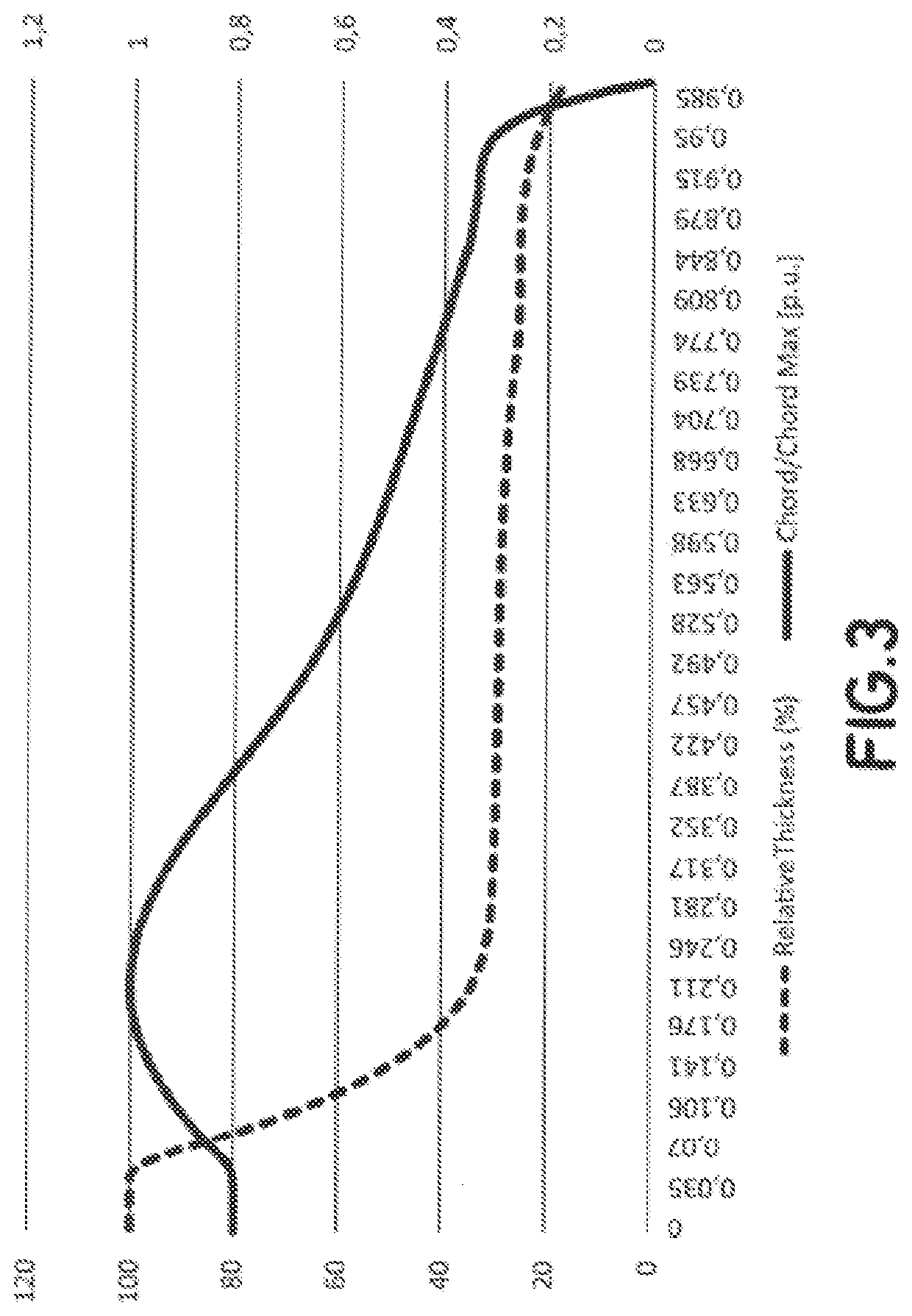
[0065]In the following an example of a wind turbine blade according to the invention is given. The distribution of chord length and relative thickness t / c is listed in Table 1.
TABLE 1RelativeChord / ChordL (p.u)Thickness (%),Max [p.u.]01000.8018719890.0599.6366560.8033870540.10170.506650.9002179130.15148.1112020.9692379580.17641.0812480.9887769220.18638.9097650.9938695980.20635.5122890.9999206130.21634.2308410.25131.4634230.9902209470.30230.278410.946894990.35229.850440.8783541270.40229.5887430.7966815120.45229.424580.7139348730.50329.2892090.6418541270.55329.113890.5845981140.57329.0171790.5650651910.60828.7928570.5344579440.65328.3684440.4999085430.70427.6608360.4646262970.75426.6383160.428819910.80425.6477940.3924345740.85425.5819880.3610475090.88925.3492160.343694320.90525.0669480.3383785520.9523.0999170.3151215220.9721.4985040.2539617870.9820.4893550.1972606720.99518.6846070.0685972611180.012131195
PUM
 Abstract
Description
Claims
Application Information