
Portable therapeutic strengthening apparatus using adjustable resistance

a technology of adjustable resistance and therapeutic strengthening, which is applied in the direction of resistance force resistors, sport apparatus, gymnastics exercise, etc., can solve the problems of life changing effects, significant and rapid reduction of muscle strength, deconditioning effect, etc., and achieve optimal transportation and portability, easy wipe down of the machine, and convenient portability

Active Publication Date: 2021-08-12
TURNER JENNIFER JANE
View PDF11 Cites 8 Cited by
  • Summary
  • Abstract
  • Description
  • Claims
  • Application Information

AI Technical Summary

Benefits of technology

The patent describes a device for training or workouts that has a connecting means to move a guide member between two ends. The device also has a resistance that a user can adjust to make it easier or harder to move the guide member. The device also has removable liners that can be magnetically aligned to prevent loss. The technical effect of this patent is to provide a device that can adjust resistance to make it easier or harder for a user to move the guide member, which can help in training or workouts. The removable liners can also be easily replaced to ensure the device is always ready for use.

Problems solved by technology

The significant and rapid reduction of muscle strength otherwise known as the de-conditioning effect, can be extreme for bed ridden patients and can have life changing effects.
Physiotherapists have limited time and are under a huge amount of pressure to successfully rehabilitate these patients and get them home quickly.
However, whilst resistance bands are portable and inexpensive, many patients find them too difficult to hold in the correct position for doing leg strengthening exercises.
Furthermore, injuries have been reported, whereby the band may snap, causing injury to the skin or eyes, the band may dig into fragile skin on the outside edge of the foot causing pressure damage or the user may also become tired and release a grip on one side of the band thus incurring injury.
It is also easy for an inexperienced user to use the resistance band incorrectly, applying resistance to an incorrectly executed exercise rendering the exercise ineffective and potentially damaging.
However, such weights applied for example around a user's ankle can damage fragile patient's skin.
Static bicycles are expensive, heavy and awkward to move longer distances and these gym-style apparatuses require a user to perform the exercise with both lower limbs together.
There are many patients for example, those with lower limb fractures in plaster, splints or external fixators, spinal injuries, stroke, those lacking core stability and control, that these are not suitable for and are better served by equipment that enables the use of one leg at a time.
It is a further problem that some patients need to be restricted to bed rest due to their condition, this causes complications to be able to exercise the leg muscles sufficiently as they cannot weight bear or do standing exercises.
Known static gym-style devices cannot be used on a bed or whilst the user is sitting in a chair.
However, these are not lightweight, and due to having irregular metal edges can incur tissue damage from sharp edges, increasing the risk of infection by users.
Such devices are not safe enough for unsupervised use for many patient groups.
It is a problem with known strengthening exercises which employ movement along a horizontal plane against resistance that the machines only have a foot plate and do not support the leg adequately to allow for unsupervised use by weaker patients.
This is problematic since the force exerted by a user transfers pressure through the heel area which is at risk of breaking down in those that are frail and on sustained bed rest.
It is a further problem with prior art exercise devices which employ movement along a horizontal plane against resistance that they do not include stops or means to limit the user's joint movement when using the device.
Thus, a user can engage in physical movement of their leg beyond what is appropriate for their condition thus potentially causing muscle or joint damage.
Known devices are typically configured to exercise either the quadriceps or the hamstrings and lack the versatility to be used interchangeably for both.

Method used


Image

  • Portable therapeutic strengthening apparatus using adjustable resistance
  • Portable therapeutic strengthening apparatus using adjustable resistance
  • Portable therapeutic strengthening apparatus using adjustable resistance

Examples


first embodiment

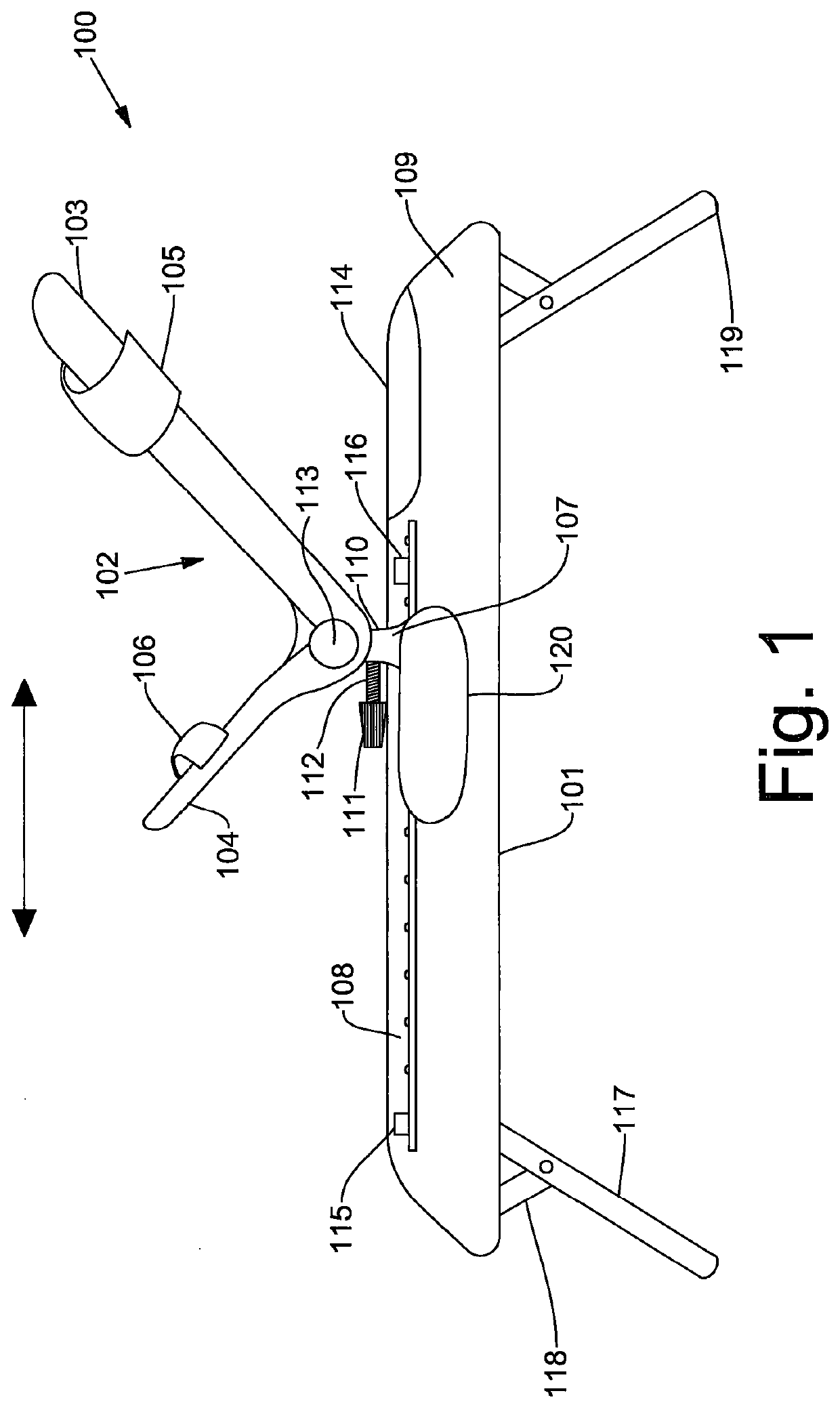
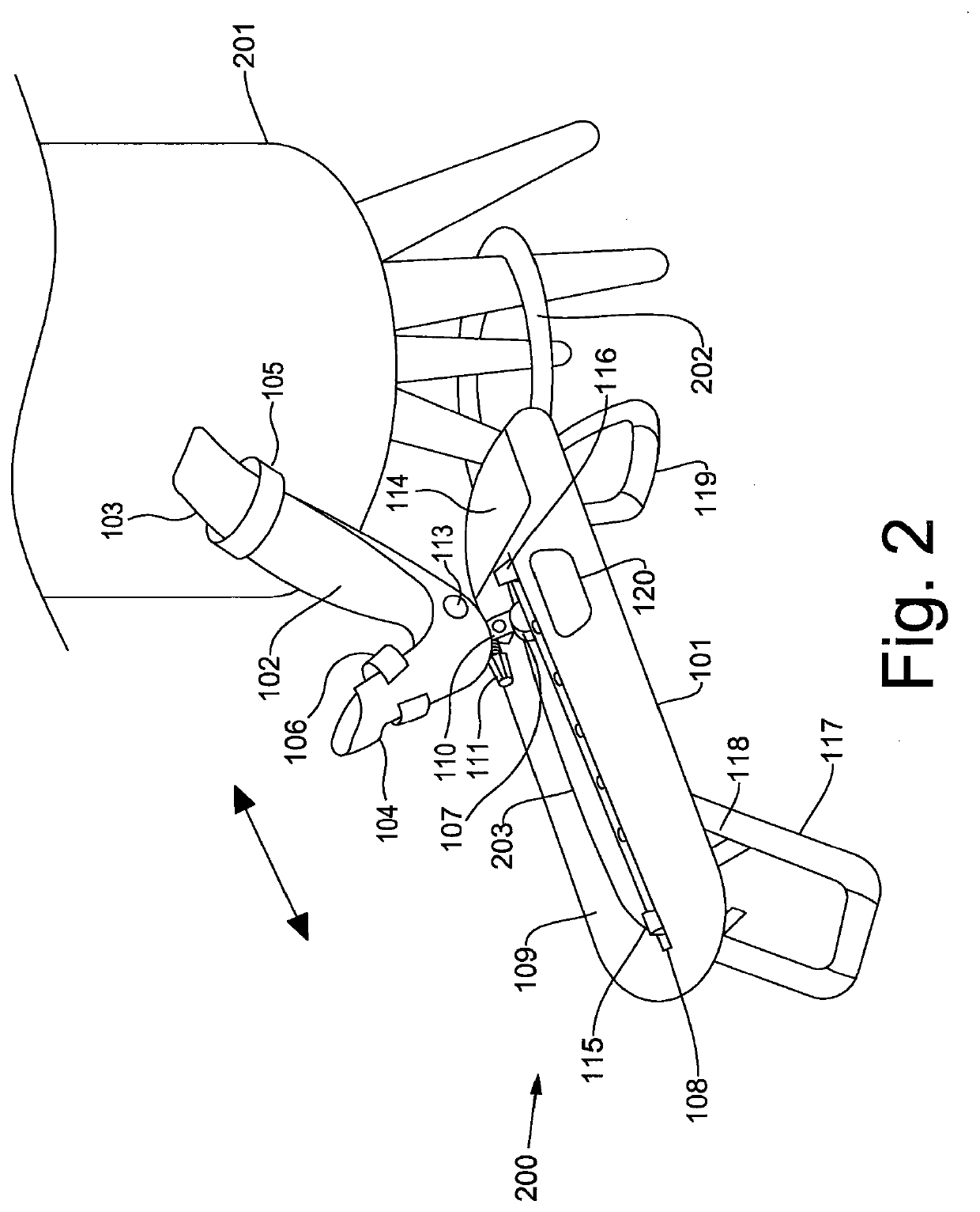
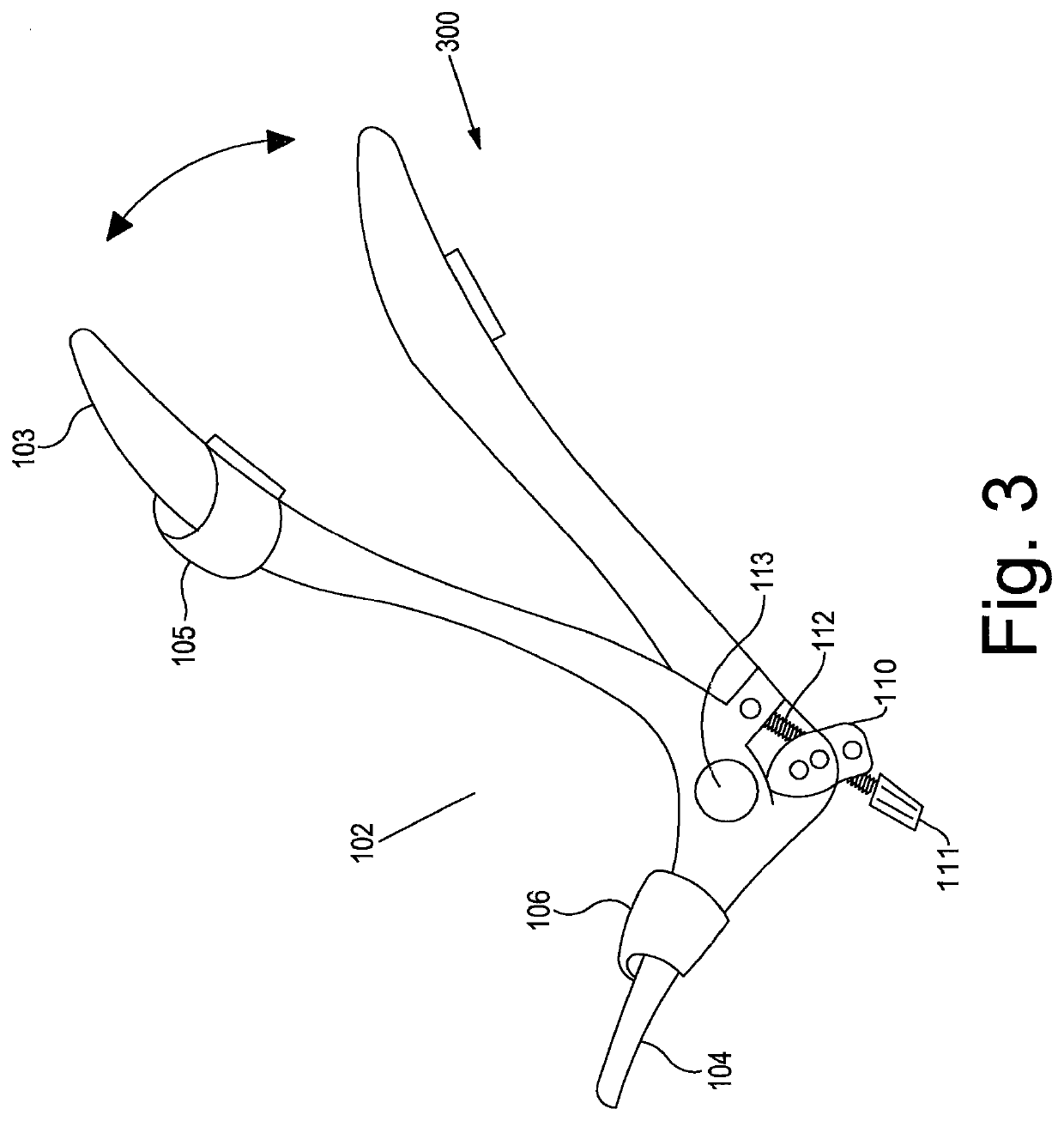
[0107]Referring to FIG. 1 herein there is shown a side view of the device 100 according to the present invention for use by a seated user to work the quadriceps muscles. The device comprises an elongate body 101 having a leg rest 102 comprising a calf support 103 and foot support 104. Straps 105 and 106 are applied around the calf and the foot respectively to fasten a user's leg to the device. The leg rest 102 is attached to a trolley 107 mounted on a friction-free longitudinal rail 108 which runs the predominant length of the elongate body 101, such that the trolley can move forward and backward along said longitudinal rail 108 in the direction of the arrow. Moving the trolley 107 longitudinally forward is against the resistance of the resistance cords described in FIG. 4.

[0108]The friction-free rail is affixed inside the device under a wipeable external cover 109. Attachment of the leg rest 102 to the friction-fee rail 108 mounted within the elongate body 101 is via pivot joint 11...

second embodiment

[0121]Referring to FIG. 7 herein there is shown a perspective view of the apparatus of the present invention. The apparatus 700 comprises an elongate body 701 having first 702 and second 703 ends. The apparatus is mounted on a pair of legs 704 in adjustable attachment to the body of the device 701 about pivot points 705. The legs have rubber stoppers 706 or rubber feet to increase friction between the apparatus and the device on which it is placed to prevent the apparatus from slipping. The legs may further comprise joining clips 707 which permit two individual apparatus 700 to be joined together or may assist in joining the device to an anchor point for stability e.g. a chair. The legs are foldable beneath the device so that it can be used folded flat for storage.

[0122]The upper surface of the elongate body 701 is a molded plastic shell of polyurethane or an aluminium extrusion 708 over which a nylon slide plate or trolley 709 is located. The nylon slide plate 709 provides a pivota...

third embodiment

[0139]Referring to FIG. 17 herein there is shown a perspective view of the apparatus in accordance with the present invention. The apparatus 1700 comprises an elongate body 1701 having first 1702 and second 1703 ends. The apparatus is mounted on a pair of legs 1704 in adjustable attachment to the body of the device 1701 about pivot points 1705. The legs have stoppers or feet 1706 made from a thermoplastic elastomer (TPE) plastic to increase friction between the apparatus and the device on which it is placed to prevent the apparatus from slipping. The legs may further comprise joining clips 1707 which permit two individual apparatus 1700 to be joined together or may assist in joining the device to an anchor point for stability e.g. a chair. The legs are foldable beneath the device so that it can be used folded flat for storage.

[0140]The upper surface of the elongate body 1701 is an aluminium extruded body 1708 over which an aluminium slide plate or trolley 1709 is located. The alumin...


PUM


Abstract

A lightweight, portable leg strengthening apparatus includes a footplate and calf support which form a leg rest, a top a friction free sliding element running longitudinally along and supported on a rectangular base. The leg rest is hinged at its attachment to the sliding element to allow a longitudinal tilting movement. The leg rest has adjustability at the hinge point at the ankle to enable alterations in the foot position. The leg rest has a removable heel support which provides the ability for either no pressure of full pressure to be exerted through the heel area of the user. The leg rest is able to be rotated 180° to allow for the user to either push the leg rest a top the guide member away from the user to allow the user to work their quadriceps, or may be pulled towards the user allowing the user to work their hamstring. The apparatus uses resistance material / rubber cords or springs attached via a plate to a steel cable, travelling via an aperture in the end of the device to the back of the sliding element a top the body of the device to create tension as the leg rest a top the sliding element is moved longitudinally along the body of the device. Resistance can be varied and progressed by using different numbers of resistance cords / springs. Organ stop devices are used to engage and disengage the resistance means so that the user has no need to have physical contact with said resistance means. A movable block on the rear of the device behind the sliding element prevents a patient flexing the knee and hip further than is appropriate for them. Fold away legs that are rotated out from under the device and locked into place make the device versatile for using whilst seated or folded away for use on a bed. A contact sensor at the front of the device enables visual display of number of repetitions achieved on a screen at the rear of the apparatus.

Description

FIELD OF THE INVENTION[0001]The present invention relates to a portable device for strengthening leg muscles.BACKGROUND OF THE INVENTION[0002]When a person is unwell or injured and is immobile for a period, they can lose up to 20% of muscle strength within the first 7 days. It is common for patients in hospital to be in bed for extended periods of time, especially those who are more elderly and frail, have suffered fractures or have complex multi pathologies. The significant and rapid reduction of muscle strength otherwise known as the de-conditioning effect, can be extreme for bed ridden patients and can have life changing effects. Physiotherapists have limited time and are under a huge amount of pressure to successfully rehabilitate these patients and get them home quickly. There is limited effective strengthening equipment available to use with patients and there is a need for a better solution to speed up the rehabilitation process.[0003]In order to treat de-conditioned muscles,...

Claims


Application Information

Patent Timeline
Patent Type & Authority Applications(United States)
IPC IPC(8): A63B23/08A63B21/00A63B21/02A63B21/04A63B21/055A63B23/035
CPCA63B23/085A63B21/154A63B21/023A63B21/4034A63B21/4047A63B2225/09A63B21/0428A63B21/0552A63B23/03508A63B2208/0252A63B21/4039A63B21/00065A63B21/0442A63B21/0557A63B21/1609A63B21/1672A63B21/4011A63B21/4015A63B21/4031A63B21/4045A63B23/0417A63B2071/0072A63B2208/0233A63B2208/0238A63B2210/02A63B2210/50A63B2225/093A63B23/04
Inventor TURNER, JENNIFER-JANE
Owner TURNER JENNIFER JANE
Learn More