
Printing device

a printing device and printing plate technology, applied in printing, inking apparatus, other printing apparatus, etc., can solve the problems of increasing the gap between the feeding roller and the pressing roller, reducing the diameter, and gradually worn down the printing pla

Active Publication Date: 2021-08-12
BIXOLON
View PDF0 Cites 0 Cited by
  • Summary
  • Abstract
  • Description
  • Claims
  • Application Information

AI Technical Summary

Benefits of technology

The present invention pertains to a printing device with enhanced ability to transfer paper smoothly while maintaining quality of printing. It does this by accurately estimating the replacement time of a flattening roller. The device has two ends, one upstream and one downstream, where adhesive can accumulate easily. The device is not affected by the formation of protruding portions, which makes it easier to transfer paper smoothly.

Problems solved by technology

Meanwhile, the feeding roller configured to transfer the recording paper and the flattening roller configured to perform printing are gradually worn down as hours of use increase such that diameters decrease.
In the case of the feeding roller, as the diameter gradually decreases, a gap between the feeding roller and the pressurizing roller increases such that a problem in transfer of the recording paper is caused.
However, in conventional printing devices, it is difficult to estimate an accurate replacement time such that a serious problem, such as replacement after printing qualities are degraded, is caused.
However, since the recording paper is provided as a roll, a surface opposite to an adhesive surface is soiled with the adhesive.
A problem caused by the adhesive soiled on the surface opposite the adhesive surface is not recognized at all such that research for solving a variety of such problems caused thereby is poor.
Due to the phenomenon, the recording paper is not stably discharged through an outlet and is held by a particular component such that a jamming phenomenon is caused.

Method used


Image

  • Printing device
  • Printing device
  • Printing device

Examples


Embodiment Construction

[0060]Hereinafter, detailed embodiments of the present invention will be described in detail with reference to the drawings. However, the concept of the present invention is not limited to the disclosed embodiments, and one of ordinary skill in the art may easily implement retrogressive invention or other embodiments included in the conceptual scope of the present invention through addition, change, deletion, and the like of another component without departing from the conceptual scope, which should be included in the conceptual scope of the present invention.

[0061]Also, in the drawings with respect to the embodiments, elements having the same function within the same conceptual scope will be referred to as the same reference numerals.

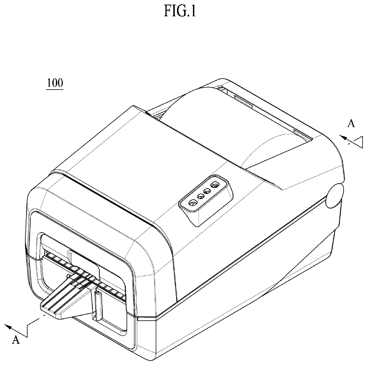
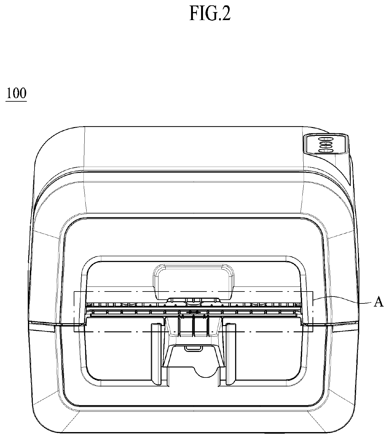
[0062]FIG. 1 is a schematic perspective view illustrating a printing device according to one embodiment of the present invention, and FIG. 2 is a schematic front view illustrating a printing device according to one embodiment of the present invention.

[...


PUM


Abstract

Disclosed is a printing device including a main body portion including a body portion configured to provide an internal space in which recording paper for printing certain information thereon is transferred and an opening or closing portion configured to control opening or closing of the internal space, a printing portion configured to print the certain information on the recording paper transferred in the internal space, and a recording paper separation portion located on a downstream side of the printing portion and configured to cut or cut off and separate recording paper on which particular information is printed by the printing portion from the other recording paper. Here, the main body portion includes a protruding portion configured to prevent an adhesive attached to the surface opposite the adhesive surface from being accumulated by decreasing a contact area with the surface opposite the adhesive surface.

Description

CROSS-REFERENCE TO RELATED APPLICATION[0001]This application claims priority to and the benefit of Korean Patent Application Nos. 10-2020-0016356, filed on Feb. 11, 2020, 10-2020-0016357, filed on Feb. 11, 2020, 10-2020-0051341, filed on Apr. 28, 2020, 10-2020-0051342, filed on Apr. 28, 2020, 10-2020-0051343, filed on Apr. 28, 2020, the disclosure of which is incorporated herein by reference in its entirety.BACKGROUND1. Field of the Invention[0002]The present invention relates to a printing device, and more particularly, to a printing device configured to implement smooth transfer of recording paper, to prevent an accumulation of an adhesive, and to prevent a phenomenon that an end of the printing paper is rolled so as to prevent printing qualities from being influenced.2. Discussion of Related Art[0003]A thermal printer is a type of nonimpact printer in which a particular recording paper which reacts to heat is used and heat is applied to the recording paper using a printer head to...

Claims


Application Information

Patent Timeline
Patent Type & Authority Applications(United States)
IPC IPC(8): B41J15/04B41J2/32
CPCB41J15/04B41J2202/30B41J2/32B41J11/0045B41J11/703
Inventor KIM, JIN GWANKIM, JIN KOOK
Owner BIXOLON
Learn More