
Modular housing system

Active Publication Date: 2021-08-12
LIFTING POINT CONSTR TECH PTY LTD
View PDF0 Cites 1 Cited by
  • Summary
  • Abstract
  • Description
  • Claims
  • Application Information

AI Technical Summary

Benefits of technology

The patent describes a modular housing system that includes an internal chassis and an external chassis. The external chassis has columns and cross-beams that form a frame around the internal chassis, creating more space inside and increasing the overall volume of the structure. The strength of the chassis ensures the dimensions of the housing system are stable and reliable. The technical effect is a more efficient and stable housing system with increased space and stability.

Problems solved by technology

Particularly in remote areas, and areas devastated by natural disaster where access, resources and manpower may be severely limited.

Method used


Image

  • Modular housing system
  • Modular housing system
  • Modular housing system

Examples


Embodiment Construction

[0153]The term “chassis” is understood herein to define a frame, or skeleton to the modular house that provides a structural framework as a basis from which additional panels and members can be engaged and supported.

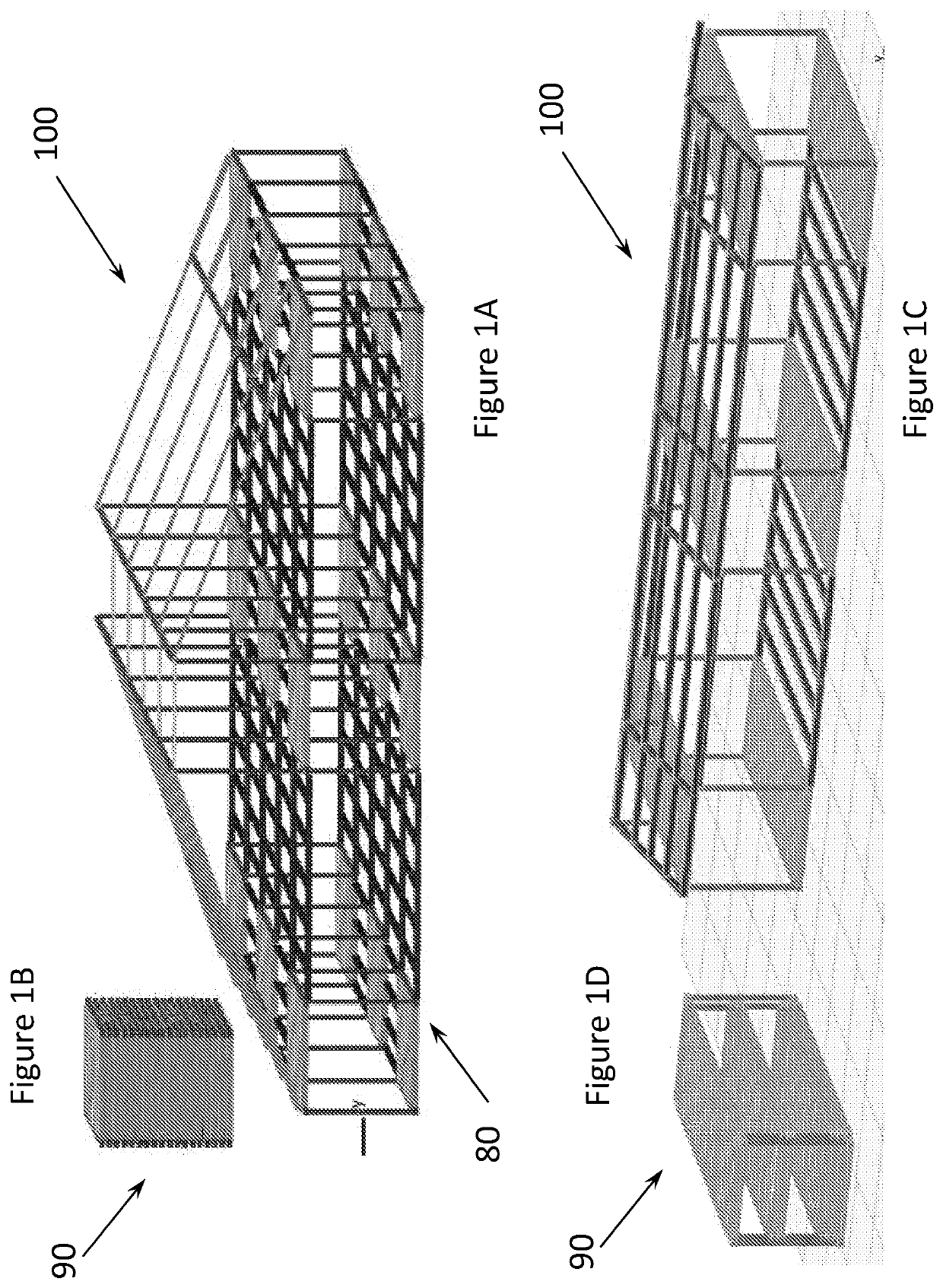
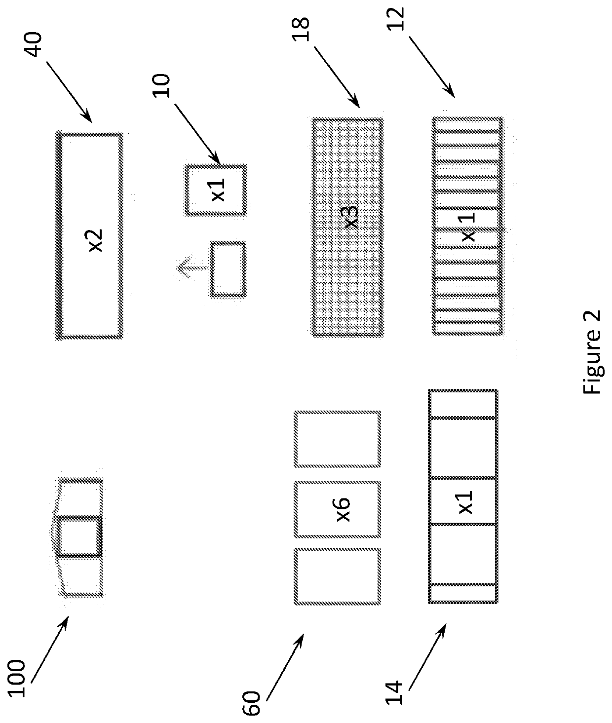
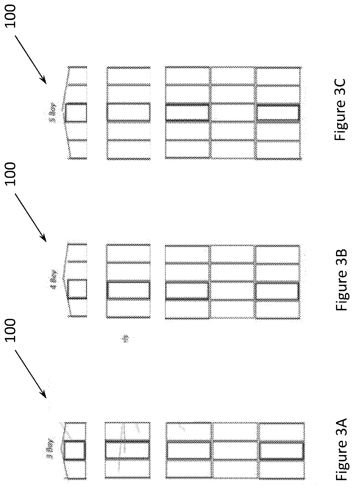
[0154]Referring generally to FIGS. 1A and 1C, the invention provides a modular housing system 100 comprising a structural framework 80, the framework 80 comprising an internal chassis 10 as a core structural element, the internal chassis 10 including; a first ladder frame 12 that defines a base; at least two extendable columns 50; and a second ladder frame 14 engaged to the first ladder frame 12 via the at least two extendable columns 50, such that at least one of a distance and an angle θ between the first ladder frame 12 and the second ladder frame 14 is adjustable. In some embodiment, the modular housing further comprises a roof supported by the framework 80. In some embodiments the framework 80 is adjusted to provide a roof formed from an upper portion of the framewo...


PUM


Abstract

The invention is directed broadly to a modular housing system having a structural framework comprising an internal chassis as a core structural element, the internal chassis including: a first ladder frame that defines a base; four columns at least two being extendable columns; and a second ladder frame engaged to the first ladder frame via the four columns, such that at least one of a distance and an angle between the first ladder frame and the second ladder frame is adjustable to define a usable volume of the structural framework.

Description

TECHNICAL FIELD[0001]The invention relates to a modular housing system and a method of erecting a modular house using the modular housing system.[0002]The invention also relates to an extendable column and a self-jacking column that can be used in combination with the modular housing system although not exclusively so.BACKGROUND[0003]Affordability and availability are two restrictive factors that determine whether housing can be provided and erected in areas where it is most needed. Particularly in remote areas, and areas devastated by natural disaster where access, resources and manpower may be severely limited.[0004]The present modular housing system was conceived with these shortcomings in mind.[0005]Unless defined otherwise, all technical and scientific terms used herein have the same meaning as commonly understood by one of ordinary skill in the art to which this invention belongs. Although any methods and materials similar or equivalent to those described herein can also be us...

Claims


Application Information

Patent Timeline
IPC IPC(8): E04B1/343E04B1/348E04G11/54E04G21/16E04H1/00E04H1/04
CPCE04B1/34326E04B1/3483E04G11/54E04B2001/2439E04H1/005E04H1/04E04G21/16E04G21/14E04B2001/34884E04B1/34317
Inventor MULLANEY, RYAN JARVISHOWELL, JAMES RICHARDMULLANEY, NICHOLAS BRUCE
Owner LIFTING POINT CONSTR TECH PTY LTD
Learn More