

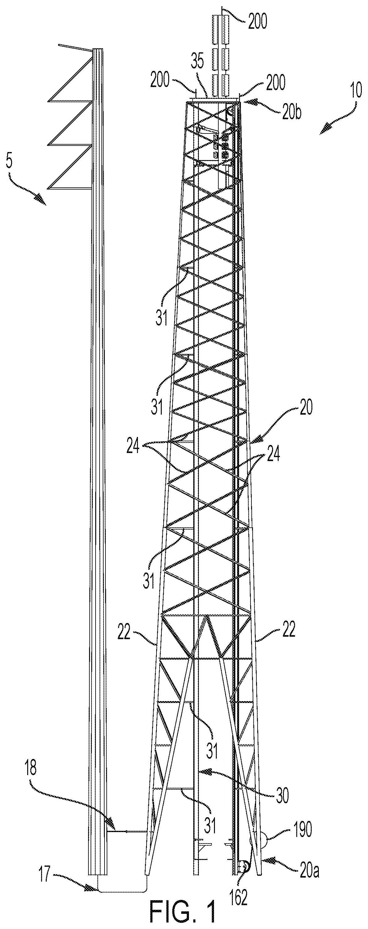
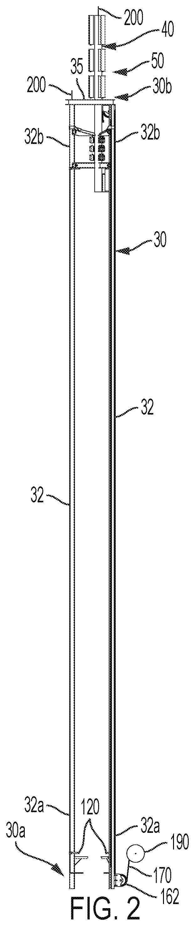
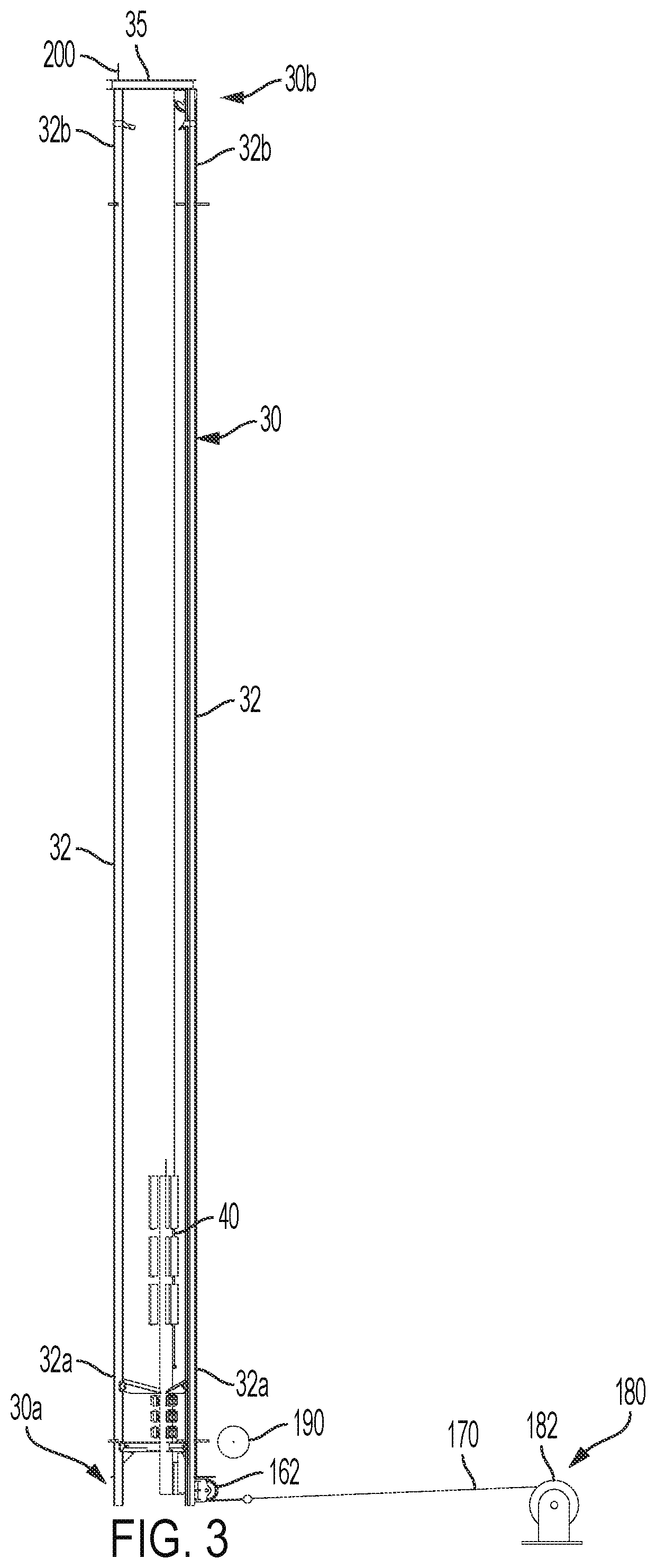
Utility structure with retractable mast
a technology of utility structure and mast, which is applied in the direction of towers, antennas, buildings, etc., can solve the problems of increasing the difficulty of telecommunications service providers in locating towers, radios and antennas or other network devices on existing electrical power transmission towers that may require structural modification, and the structural capacity of existing electrical power transmission structures may not be strong enough to support such additional loads, etc., to achieve convenient and safe access and increase the height of antenna mounting.
- Summary
- Abstract
- Description
- Claims
- Application Information
AI Technical Summary
Benefits of technology
Problems solved by technology
Method used
Image

Examples
Embodiment Construction
[0045]The present invention will now be described more fully hereinafter with reference to the accompanying figures, in which embodiments of the invention are shown. This invention may, however, be embodied in many different forms and should not be construed as limited to the embodiments set forth herein. Like numbers refer to like elements throughout. In the figures, certain components or features may be exaggerated for clarity, and broken lines illustrate optional features or operations unless specified otherwise. In addition, the sequence of operations (or steps) is not limited to the order presented in the figures and / or claims unless specifically indicated otherwise. Features described with respect to one figure or embodiment can be associated with another embodiment or figure although not specifically described or shown as such.
[0046]Unless otherwise defined, all terms (including technical and scientific terms) used herein have the same meaning as commonly understood by one of...
PUM
 Abstract
Description
Claims
Application Information