
Position detecting system and position detecting method

Pending Publication Date: 2021-08-12
THE SHIMIZU CONSTRUCTION CO LTD
View PDF0 Cites 0 Cited by
  • Summary
  • Abstract
  • Description
  • Claims
  • Application Information

AI Technical Summary

Benefits of technology

The invention provides a system and method for accurately detecting a target object's position and shape in three dimensions. Additionally, the system can easily associate identification information with the target object.

Problems solved by technology

However, the aforementioned detection techniques are techniques for estimating positions using the intensity of electromagnetic waves or the like received by communication terminals provided at target objects, and it may not be possible to detect accurate positions of target objects since the positions are obtained through estimation.
According to the aforementioned detection techniques, although it is possible to estimate the positions of target objects that move along with the communication terminals, it is not possible to recognize accurate sizes of the target objects.
Further, since it is only possible to estimate the positions of target objects, it is not possible to detect the size of a target object, such as whether operators who are carrying the communication terminals are moving alone or whether the operators are carrying a large load on a carriage.
Therefore, in a case in which the aforementioned techniques for detecting target objects are used for navigation in a building, for example, it is not possible to ascertain the size of a moving target object and thus to perform a process of excluding locations having restrictions in size for passing therethrough from a navigation route.
As a result, the sizes of target objects for which navigation can be performed are limited, and it is not possible to use the techniques to carry loads in buildings.

Method used


Image

  • Position detecting system and position detecting method
  • Position detecting system and position detecting method
  • Position detecting system and position detecting method

Examples


case # 1

(Case #1)

[0057]A case in which a target object indicated by a target object shape 561 includes a wireless device and a target object indicated by a target object shape 562 does not include a wireless device.

(Process F21)

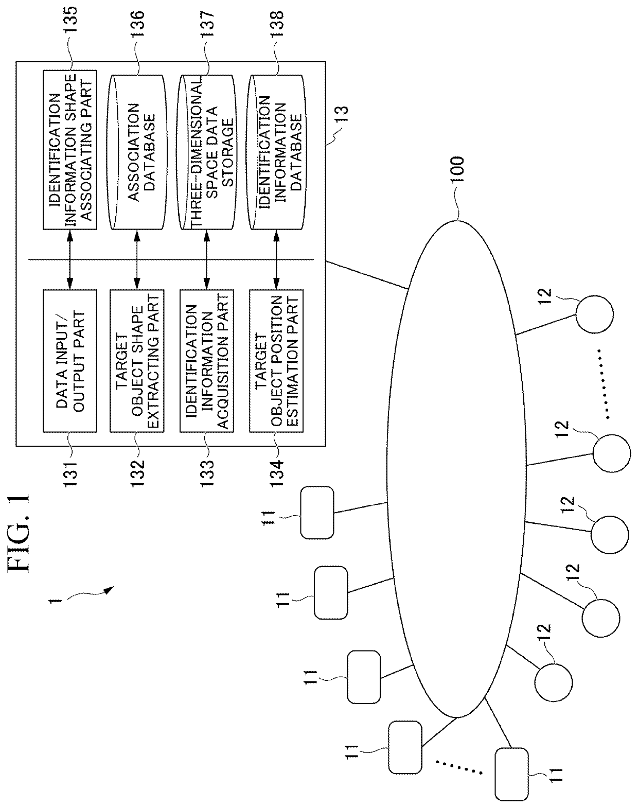
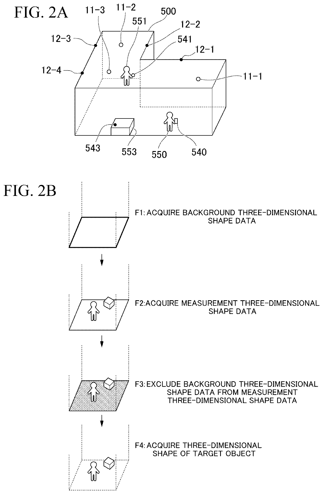
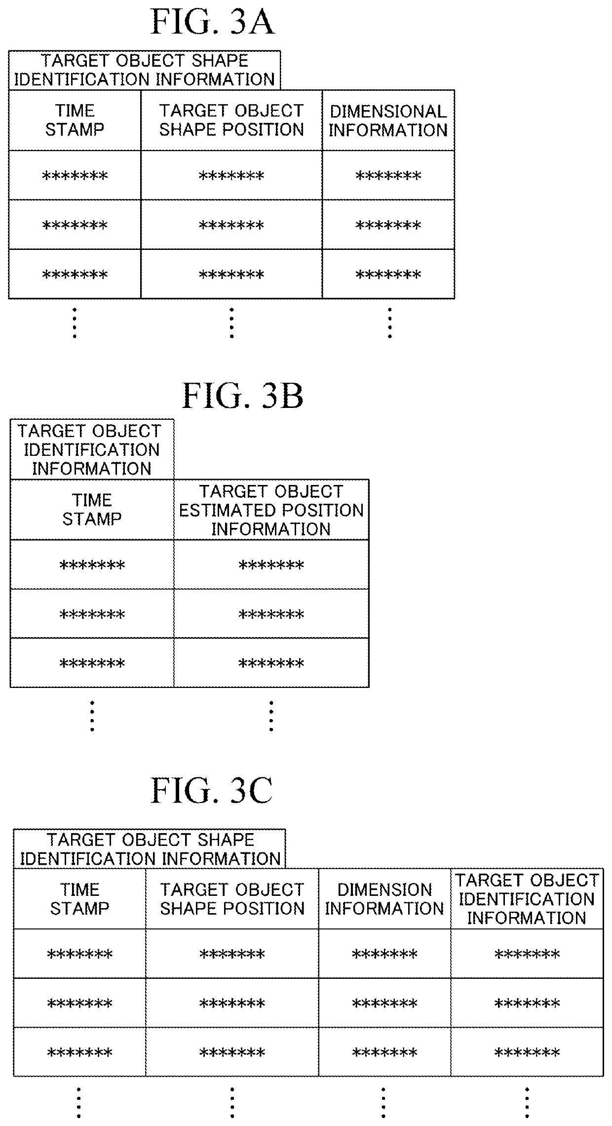
[0058]In a case in which each of the target object shapes 561 and 562 has been detected, the target object shape extracting part 132 manages the target object shapes 561 and 562 with target object shape identification information applied thereto. The identification information shape associating part 135 associates target object identification information with the target object shape 561 while the identification information shape associating part 135 does not associate any target object identification information with the target object shape 561.

(Process F22)

[0059]In a case in which the target object shape extracting part 132 detects that the target object shapes 561 and 562 have been integrated, the target object shape extracting part 132 performs management using ta...

case # 2

(Case #2)

[0062]A case in which target objects indicated by target object shapes 561 and 562 include wireless devices.

(Process F21)

[0063]In a case in which each of the target object shapes 561 and 562 has been detected, the target object shape extracting part 132 manages the target object shapes 561 and 562 with target object shape identification information applied thereto. The identification information shape associating part 135 associates target object identification information with each of the target object shapes 561 and 562.

(Process F22)

[0064]In a case in which the target object shape extracting part 132 detects that the target object shapes 561 and 562 have been integrated, the target object shape extracting part 132 manages the integrated target object shapes 561 and 562 using three-dimensional shape identification information of either the integrated target object shape 561 or 562. For example, the target object shape extracting part 132 performs management using the targe...


PUM


Abstract

This position detecting system is provided with: a target object shape extracting part which extracts a target object as a target object shape from a three-dimensional shape in an indoor space, and acquires a position of the target object shape; an identification information acquisition part which acquires, on the basis of data reported from the target object, target object identification information for identifying the target object; and an identification information associating part which associates the target object shape with the target object identification information.

Description

TECHNICAL FIELD[0001]The present invention relates to a position detecting system and a position detecting method for performing position detection of a target object in an indoor space.[0002]Priority is claimed on Japanese Patent Application No. 2018-144086, filed Jul. 31, 2018, the content of which is incorporated herein by reference.BACKGROUND ART[0003]In the related art, various methods for detecting positions of target objects in buildings or the like have been studied. For example, there are many position estimating techniques using communication terminals such as beacons, wireless tags, WiFi electromagnetic waves, geomagnetism, indoor messaging systems (IMESs), personal handy-phone systems (PHSs), or the like and many configurations as combinations thereof (see Patent Document 1, for example).[0004]However, the aforementioned detection techniques are techniques for estimating positions using the intensity of electromagnetic waves or the like received by communication terminal...

Claims


Application Information

Patent Timeline
IPC IPC(8): G01C21/20G01S17/06G01S7/481G01S5/14
CPCG01C21/206G01S7/4811G01S17/06G01S5/14G08G1/005G01S17/89G01S7/4802
Inventor MATSUMOTO, TAKASHI
Owner THE SHIMIZU CONSTRUCTION CO LTD
Learn More