Two-shaft gas turbine

a gas turbine and two-shaft technology, applied in the direction of machines/engines, stators, mechanical equipment, etc., can solve the problems of large energy loss, and achieve the effects of reducing size (axial length), reducing energy loss, and reducing energy consumption

Inactive Publication Date: 2021-08-19
MITSUBISHI HEAVY IND LTD
View PDF7 Cites 1 Cited by
  • Summary
  • Abstract
  • Description
  • Claims
  • Application Information

AI Technical Summary

Benefits of technology

[0010]According to the two-shaft gas turbine of an aspect of the present disclosure, because the strut provided in the intermediate flow path concurrently functions as the first stage stator blade of the low-pressure turbine, the size (axial length) can be reduced and the turbine can be made compact.
[0011]Furthermore, in the two-shaft gas turbine according to an aspect of the present disclosure, an area enlargement ratio B / A of the intermediate flow path at upstream of the strut is set to be greater than an area enlargement ratio C / B of the intermediate flow path within the range of the strut in the axis direction. Thus, the flow of the combustion gas can be slowed down, after passing through the outlet of the final stage rotor blade of the high-pressure turbine, and before entering the strut. Thus, loss within the strut can be reduced.
[0012]In this way, according to the two-shaft gas turbine of an aspect of the present disclosure, it is possible to realize a two-shaft gas turbine that is compact and is capable of reducing energy loss of the combustion gas.

Problems solved by technology

However, there is a problem in that a large energy loss occur due to high flow rates within the axial position range in which the strut is provided.

Method used


Image

  • Two-shaft gas turbine
  • Two-shaft gas turbine
  • Two-shaft gas turbine

Examples


first embodiment

[0023]A two-shaft gas turbine according to the first embodiment will be described below with reference to FIGS. 1 to 4. Here, the two-shaft gas turbine of the present embodiment relates to a two-shaft gas turbine suitable for use as a heavy duty gas turbine for various industrial machines, power generation devices, and the like. Also, the two-shaft gas turbine of the present disclosure may be used as a gas turbine for other applications such as an aircraft (an aircraft engine).

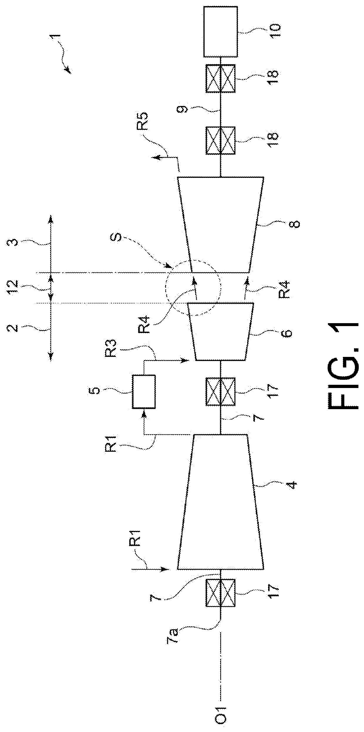
[0024]As illustrated in FIG. 1, a two-shaft gas turbine 1 according to the present embodiment is provided with a compressor drive side turbine portion (gas generator portion) 2, and an output side turbine portion (power turbine portion) 3. The two-shaft gas turbine 1 is configured to drive a load device 10, such as an industrial machine and a generator motor, by the output side turbine portion 3. Also, the two-shaft gas turbine 1 is provided with a control device, a turbine casing containing the compressor dri...

second embodiment

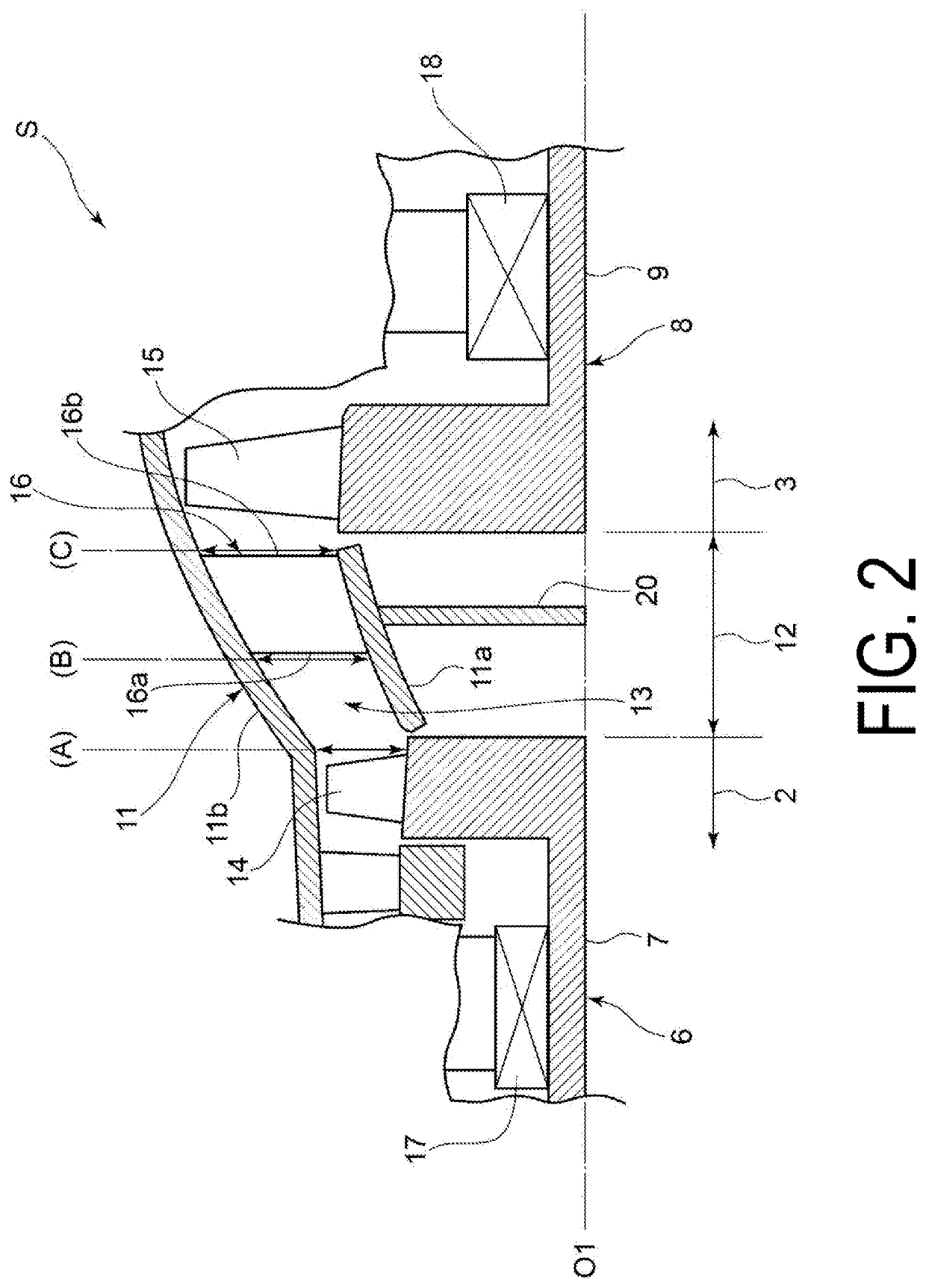
[0064]Next, A two-shaft gas turbine according to the second embodiment will be described below with reference to FIGS. 5 to 9 (and FIGS. 1, 2, 3, and 4). Here, with respect to the configuration of the two-shaft gas turbine of the first embodiment, the shape and arrangement of the stator blade in the final stage of the high-pressure turbine of the two-shaft gas turbine of the present embodiment are different, and other configurations are the same. Thus, in the present embodiment, the same components as those of the first embodiment are denoted by the same reference signs, and a detailed description thereof will be omitted.

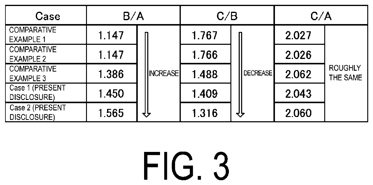
[0065]In the first embodiment described above, the area enlargement ratio B / A of the intermediate flow path 13 at upstream of the strut 16 is set to be greater than the area enlargement ratio C / B of the intermediate flow path 13 within the range of the strut 16 in the axis O1 direction. Thus, the flow of the combustion gas R4 can be slowed down, after passing throug...


PUM


Abstract

A two-shaft gas turbine includes a compressor, a high-pressure turbine including a first shaft connected to a rotation shaft of the compressor, a low-pressure turbine including a second shaft separate from the first shaft, and is provided coaxially to the high-pressure turbine with an interval in an axis direction between the low-pressure turbine and the high-pressure turbine, an intermediate flow path provided between a final stage rotor blade of the high-pressure turbine and a first stage rotor blade of the low-pressure turbine in the axis direction, the intermediate flow path being configured to supply a combustion gas from the high-pressure turbine to the low-pressure turbine, and a strut disposed inside the intermediate flow path. The strut concurrently functions as a first stage stator blade of the low-pressure turbine.

Description

CROSS-REFERENCE TO RELATED APPLICATIONS[0001]This application claims the benefit of priority to Japanese Patent Application Number 2020-024293 filed on Feb. 17, 2020. The entire contents of the above-identified application are hereby incorporated by reference.TECHNICAL FIELD[0002]The present disclosure relates to a two-shaft gas turbine.RELATED ART[0003]In the related art, a known two-shaft gas turbine is provided with a high-pressure turbine and a low-pressure turbine on separate shafts and supplies a combustion gas that has passed through the high-pressure turbine to the low-pressure turbine through an intermediate duct.[0004]For example, heavy duty two-shaft gas turbines have many advantages, such as being able to discretionarily adjust and select the rotation speed of the rotation shaft, being able to implement drive in a wide range of rotation speeds, being able to start a startup motor with little startup torque when starting the startup motor that rotates a compressor-driving...

Claims


Application Information

Patent Timeline
Patent Type & Authority Applications(United States)
IPC IPC(8): F02C3/10F02C3/04F02C3/13
CPCF02C3/10F02C3/04F02C3/13F05D2240/30F05D2240/60F05D2240/50F05D2220/32F01D9/02F01D9/041F01D5/143F05D2220/3215F01D25/30Y02T50/60
Inventor KIMURA, YASUNORI
Owner MITSUBISHI HEAVY IND LTD
Why Eureka
Try Eureka