Liquid ejection device and liquid container
- Summary
- Abstract
- Description
- Claims
- Application Information
AI Technical Summary
Benefits of technology
Problems solved by technology
Method used
Image

Examples
first embodiment
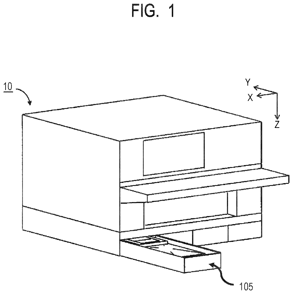
[0020]FIG. 1 is a schematic perspective view illustrating the external configuration of a liquid ejection device 10. As illustrated in FIG. 1, a mounting body 105 (the mounting body 105 is configured by storing a liquid container 100 including a bag-shaped member 110 and a connecting member 120 in a case 61, which will be described in detail in FIGS. 2A to 2C) is configured to be attachable to and detachable from the liquid ejection device 10. The liquid ejection device 10 is, for example, an ink jet printer and forms an image by ejecting ink droplets from a recording head (not illustrated) included in the liquid ejection device 10 to record ink dots on a recording medium. Ink may be, for example, a pigment ink containing a coloring component. The recording medium is, for example, printing paper. The liquid container 100 includes the bag-shaped member 110 made of a flexible bag body and the connecting member 120 that connects the bag-shaped member 110 to the liquid ejection device 1...
second embodiment
[0041]FIGS. 6A to 6C is a schematic perspective view of a liquid container 100b that is contained in a liquid ejection device in a second embodiment. FIG. 6A is a schematic perspective view of a mounting body in which the liquid container 100b in the second embodiment is contained. The state illustrated by FIG. 6A is a state of a mounting body 105b in which the liquid container 100b is housed in the case 61. The liquid container 100b is an ink pack and includes the bag-shaped member 110 and a connecting member 120b. FIG. 6B is a schematic perspective view illustrating the appearance of the liquid container 100b removed from the case 61. As illustrated in FIG. 6B, a handle 170b includes the grip portion 171, the two coupling portions 172 and 173, the two base end portions 174 and 175, and a liquid container-side fitting portion 155b. In the connecting member 120b, the structure of the liquid container-side fitting portion 155b that is provided in the connecting member 120b is differe...
third embodiment
[0051]The electrical connecting portion may be integrated with the handle. FIG. 11 is a schematic perspective view of a mounting body 105c when a liquid container 100c is removed from the case 61 in a third embodiment. The third embodiment is an aspect in which an electrical connecting portion is provided in the handle of the first embodiment. The mounting body 105c is made up of the liquid container 100c and the case 61. A handle 170c in the liquid container 100c has the liquid container-side fitting portion 155 and an electrical connecting portion 140c. The electrical connecting portion 140c is provided at an end portion of the handle 170c in a mounting direction of the mounting body 105c. The electrical connecting portion 140c is provided on an extension line from the coupling portion 173 of the handle 170c and at a position opposite to the grip portion 171 across the base end portion 175. The electrical connecting portion 140c includes a substrate 141c configured to be connected...
PUM
 Abstract
Description
Claims
Application Information
 - Generate Ideas
- Intellectual Property
- Life Sciences
- Materials
- Tech Scout
- Unparalleled Data Quality
- Higher Quality Content
- 60% Fewer Hallucinations
Browse by: Latest US Patents, China's latest patents, Technical Efficacy Thesaurus, Application Domain, Technology Topic, Popular Technical Reports.
© 2025 PatSnap. All rights reserved.Legal|Privacy policy|Modern Slavery Act Transparency Statement|Sitemap|About US| Contact US: help@patsnap.com