Seal structure for fluid pressure device

a fluid pressure device and sealing structure technology, applied in the direction of multiple way valves, piston rings, mechanical equipment, etc., can solve the problems of high sliding resistance of packing units, and high likelihood of biting, fixation, etc., to achieve efficient reduction of sliding resistance during operation, easy to bend packing units, and increased flexibility

Inactive Publication Date: 2021-08-26
SMC CORP
View PDF0 Cites 0 Cited by
  • Summary
  • Abstract
  • Description
  • Claims
  • Application Information

AI Technical Summary

Benefits of technology

[0027]In the seal structure of the present invention, because both side surfaces of the packing unit are conical surfaces inclined in mutually opposite directions and thus the thickness of the packing unit increases in a gradual manner in the direction from the mounting section toward the sliding section, the flexibility of the packing unit is increased and the packing unit can be easily bent in a smooth and uniform manner as a whole while at the same time protrusion from the mounting groove resulting from deformation of the sliding section during pressurization by fluid pressure is unlikely to occur. Therefore, the sliding resistance during operation can be efficiently reduced while at the same time biting is unlikely to occur and the fluid pressure can be lowered by the amount of the reduction in the sliding resistance, and thus an energy-saving effect is obtainable. In addition, because a component force of the fluid pressure acts on the side surfaces of the packing unit during pressurization by the fluid pressure toward the sliding section in the packing unit, an increase in the contact pressure on the mounting section side occurring with compression of the packing unit, that is, an increase in the amount of distortion can be suppressed, and the reaction force caused by the distortion on the mounting section side can be prevented from being transmitted to the sliding section side.

Problems solved by technology

That packing unit needs to have low sliding resistance and additionally be unlikely to produce biting, fixation, or the like resulting from protrusion from the mounting groove.
The O ring, however, has the drawbacks of not only having high sliding resistance and but also being likely to produce biting, fixation, or the like resulting from twisting.
The D ring is unlikely to produce twisting, biting, fixation, or the like, in comparison with the O ring, but has the drawback of having high sliding resistance because reaction force to compression when fluid pressure acts (during pressurization) is large.
Many of the publicly known modified packing units, however, have problems of, for example, being deformed locally and in addition excessively in a thin portion, such as a constricted section, or on the contrary, being unable to obtain a sufficient advantage of reducing the sliding resistance because inadequate flexibility, and they still have room for further improvements.
In contrast, however, because the amount of protrusion from the mounting groove resulting from compression during pressurization is increased, biting, fixation, or the like is likely to occur.
Therefore, simply increasing the width of the packing unit in the radius direction to reduce the sliding resistance is unsatisfactory.

Method used


Image

  • Seal structure for fluid pressure device
  • Seal structure for fluid pressure device
  • Seal structure for fluid pressure device

Examples


Embodiment Construction

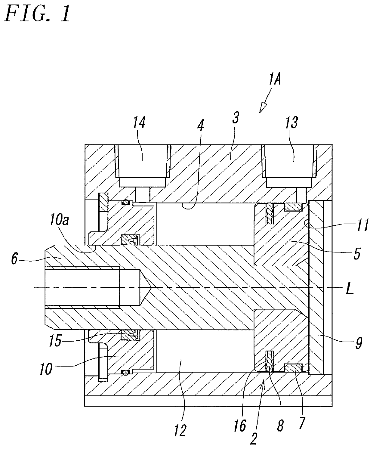
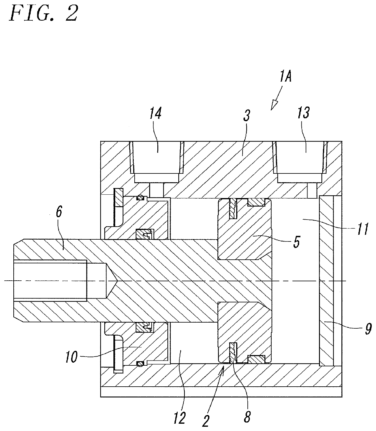
[0036]FIGS. 1 and 2 illustrate a fluid pressure device including a seal structure according to the present invention. That fluid pressure device is an air cylinder.

[0037]The air cylinder 1A includes a cylinder housing 3 whose external form has a rectangular parallelepiped shape. The cylinder housing 3 has a circular cylinder cavity 4, the cylindrical cavity 4 houses a piston 5 such that the piston 5 can freely slide along an axis L of the cylinder cavity 4, and the piston 5 is connected to a rod 6.

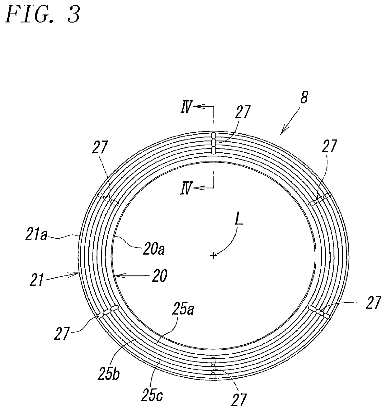
[0038]A guide ring 7 for guiding the piston 5 is mounted on the outer circumference of the piston 5, and a packing unit 8 for sealing between the outer circumference of the piston 5 and the inner circumference of the cylinder cavity 4 is mounted thereon.

[0039]A first end and a second end of the cylinder cavity 4 are hermetically blocked by a head-side end plate 9 and a rod-side end plate 10, respectively. A head-side pressure space 11 is disposed between the head-side end plate 9 and the p...


PUM


Abstract

A seal structure includes a mounting groove disposed in a first member and a packing unit housed in the mounting groove. The packing unit includes an inner circumferential mounting section and an outer circumferential sliding section. Both side surfaces of the packing unit are conical surfaces which are inclined such that their diameters gradually increase in a direction from the mounting section toward the sliding section and which are inclined in mutually opposite directions. The thickness of the packing unit increases in a gradual manner in the direction from the mounting section toward the sliding section, the thickness in the mounting section is the smallest, and the thickness in the sliding section is the largest.

Description

TECHNICAL FIELD[0001]The present invention relates to a seal structure for sealing between a first member and a second member sliding relative to each other in a fluid pressure device.BACKGROUND ART[0002]For example, in a fluid pressure device, such as a fluid pressure cylinder or an electromagnetic valve, a sliding member, such as a piston or a spool, has a mounting groove in its outer circumference, a packing unit is mounted in the mounting groove, and the sliding member slides inside a sliding cavity in a housing with the packing unit disposed therebetween. That packing unit needs to have low sliding resistance and additionally be unlikely to produce biting, fixation, or the like resulting from protrusion from the mounting groove.[0003]Examples typically used as the packing unit of that type may include an O ring and a D ring. The O ring, however, has the drawbacks of not only having high sliding resistance and but also being likely to produce biting, fixation, or the like result...

Claims


Application Information

Patent Timeline
Patent Type & Authority Applications(United States)
IPC IPC(8): F16J15/18F16J15/32F16K11/07
CPCF16J15/18F16K11/07F16J15/32F16J15/164F16J15/324F16J15/56F16K11/0712F16J9/28F16J1/008F16J15/3228F16J15/3284
Inventor KUDO, MASAYUKITAKEDA, KENICHIKAWAKAMI, MASAHIKOTAMURA, KENODAKA, TSUKASA
Owner SMC CORP
Why Eureka
Try Eureka