
Drone docking port and method of use

a drone and docking port technology, applied in the field of drone docking port and method of use, can solve the problems of delay in the response time and fuel consumption of drivers, many accidents in the us, and high cost of police, fire departments and cleanup crews to respond to these accidents, so as to reduce the inner temperature and humidity of the ddp and increase the temperature inside the ddp. , the effect of stable temperature and humidity environmen

Inactive Publication Date: 2021-09-02
SHUFF GREG DOUGLAS
View PDF55 Cites 5 Cited by
  • Summary
  • Abstract
  • Description
  • Claims
  • Application Information

AI Technical Summary

Benefits of technology

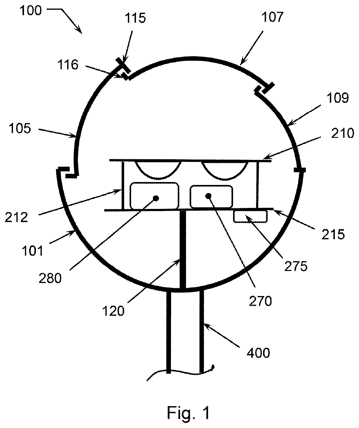
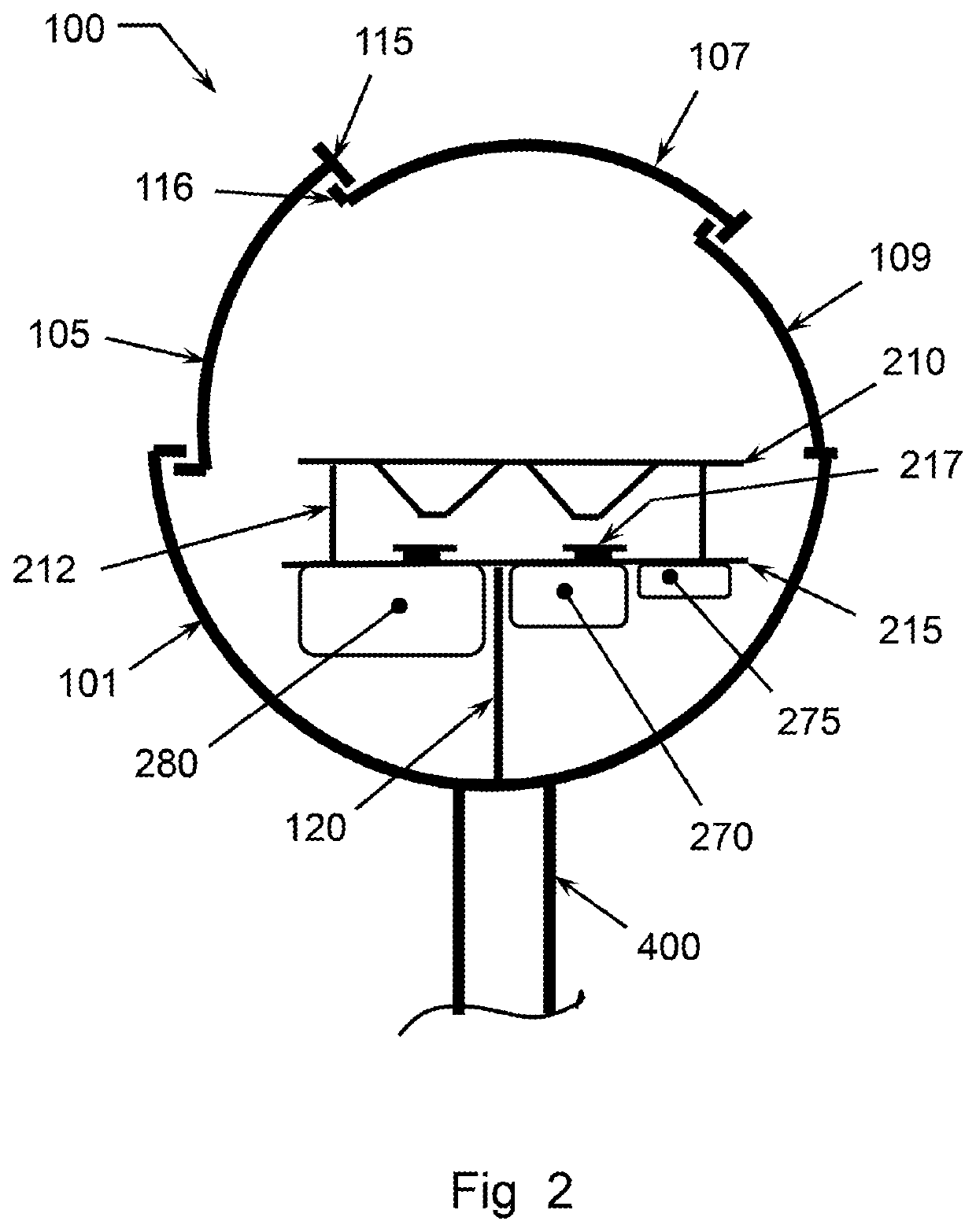
The patent describes a device called a DDP (Drones Deployment Platform) that can support drones in close proximity to incidents or at the scenes of accidents. The DDP can be attached to a vehicle or a pole and can observe drivers who are looking at the incident or accident scene. The DDP is designed to be self-sufficient, with solar panels and a battery to power it. It also has air conditioning and heating to maintain a stable temperature and humidity inside, and a weather station to detect hazardous conditions. The DDP can also have a camera to help with traffic control. The technical effects of this invention include reducing the time drivers look at an incident, increasing attention paid to driving safely, and potentially reducing vehicle wait times around an accident site.

Problems solved by technology

Many accidents occur in the US.
The cost to respond by police, fire departments and cleanup crews to these accidents is substantial, as is the cost in terms of time and fuel consumed by drivers delayed by these accidents.
This process takes considerable time and effort and can result in missing the window of opportunity to successfully capture the incident or data of interest.

Method used


Image

  • Drone docking port and method of use
  • Drone docking port and method of use
  • Drone docking port and method of use

Examples


Embodiment Construction

[0054]Reference throughout this specification to “one embodiment,”“an embodiment,” or similar language means that a particular feature, structure, or characteristic described in connection with the embodiment is included in at least one embodiment of the present invention. Thus, appearances of the phrases “in one embodiment,”“in an embodiment,” and similar language throughout this specification may, but do not necessarily, all refer to the same embodiment.

[0055]Furthermore, the described features, structures, or characteristics of the invention may be combined in any suitable manner in one or more embodiments. In the following description, numerous specific details are included to provide a thorough understanding of embodiments of the invention. One skilled in the relevant art will recognize, however, that the invention can be practiced without one or more of the specific details, or with other methods, components, materials, and so forth. In other instances, well-known structures, ...


PUM


Abstract

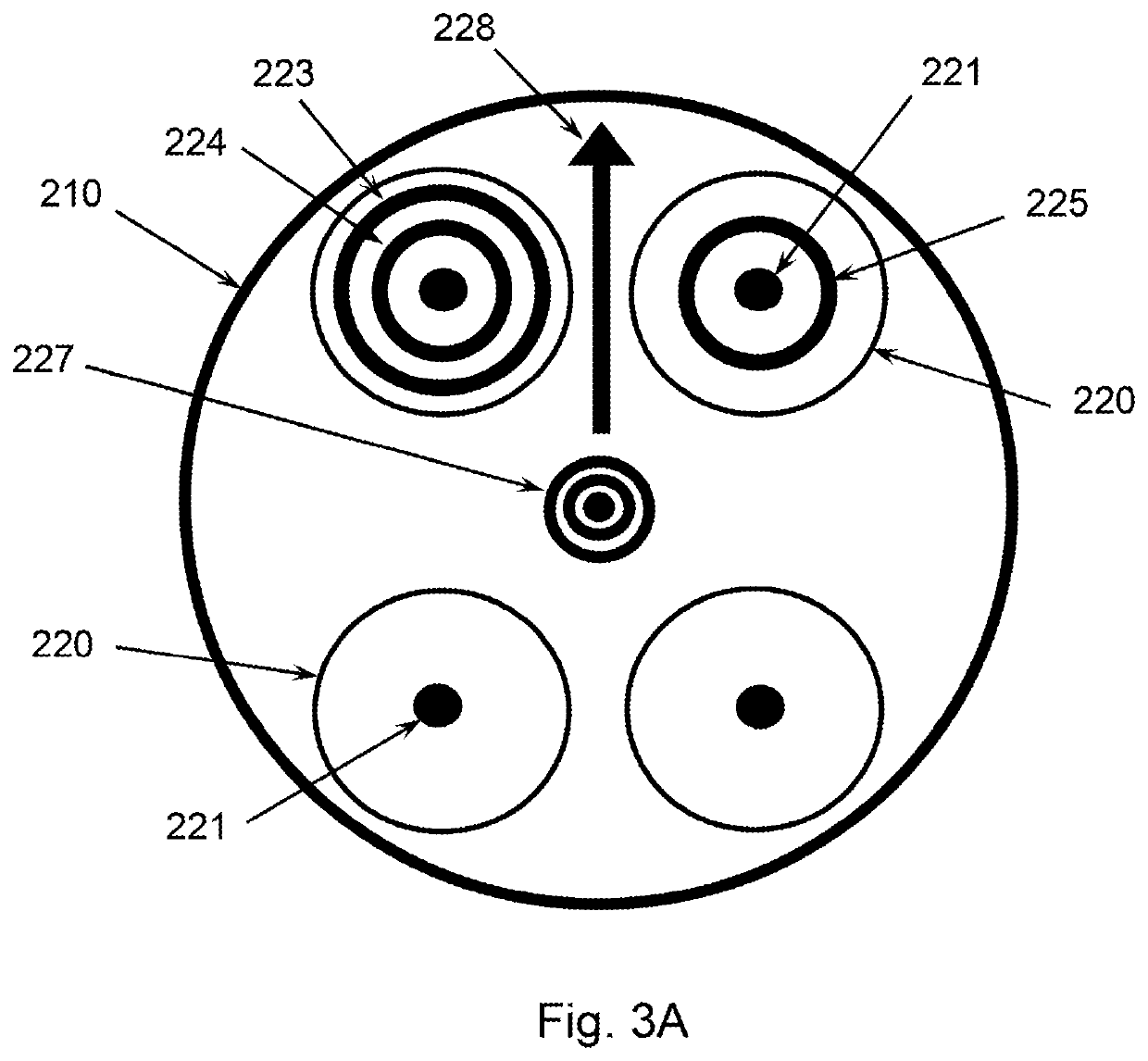
A drone docking port (DDP) preferably mounted on a pole and having an openable and closable convertible top (CT), a docking plate having integrated battery wired or wireless recharging pads, and a control module. The control module (CM) is adapted to preferably autonomously control all functions of the DDP including actuation of the CT and relay of video, audio, and flight control information between the CM and a central monitoring center and / or emergency personnel. The DDP is preferable positioned in close proximity to an intended monitoring site. When the CT is in an open position, a drone may initiate flight from the DDP and when a drone flight is completed and a drone has re-docked therein, the CT may be closed to protect the drone docked therein from external weather. The DDP may further include Electro-Optical / Infra-Red (EO / IR) cameras and sensors to detect disruptive or other predetermined behavior.

Description

FIELD OF THE INVENTION[0001]The present invention relates to docking for the facilitation of takeoff, landing and housing of drones or unmanned aerial vehicle (UAV), and more especially for drones or UAVs used in traffic control and border security and the like applications and in acquiring, storing and transmitting information regarding the same.BACKGROUND OF THE INVENTION[0002]Many accidents occur in the US. The Insurance Information Institute reports total accidents in the U.S. for 2017 at 6,452,000 resulting in approximately 1,889,000 injuries, 34,247 deaths and $4,530,000 in property damage. The cost to respond by police, fire departments and cleanup crews to these accidents is substantial, as is the cost in terms of time and fuel consumed by drivers delayed by these accidents. Moreover, time is typically of the essence in such scenarios. Present methods of deploying drones or UAVs for specific operations, such as to observe traffic incidents or security breaches generally requ...

Claims


Application Information

Patent Timeline
Patent Type & Authority Applications(United States)
IPC IPC(8): B64F1/36B64F1/00B64C39/02B64D47/08B64D27/24B64D47/04B64C25/06B60L50/60B60L53/10B60L53/35B60L53/53B60L53/51G08G5/00
CPCB64F1/362B60L2200/10B64C39/024B64D47/08B64D27/24B64D47/04B64C25/06B60L50/60B60L53/10B60L53/35B60L53/53B60L53/51G08G5/0026B64C2201/027B64C2201/042B64C2201/127B64C2201/141B64D2203/00B64F1/005B64F1/007Y02T10/70Y02T10/7072Y02T50/80Y02T90/12Y02T90/14B60L53/12B60L53/14B60L53/30G08G5/0069G08G5/0065G08G5/025G08G5/0091G08G5/0082B64U10/13B64U2201/00B64U2201/10B64U80/70B64U50/31B64U2101/30B64U70/93B64U80/25B64U50/37B64F1/222B60L58/24B60L53/302
Inventor SHUFF, GREG DOUGLAS
Owner SHUFF GREG DOUGLAS
Learn More