Support for Reciprocating Pump

a technology of power end housing and reciprocating pump, which is applied in the direction of piston pump, positive displacement liquid engine, pump parameter, etc., can solve the problems of difficult and cumbersome manufacturing and assembly of conventional power end housing, difficult access to certain areas of the housing, and easy damage to pumps

Active Publication Date: 2021-09-02
SPM OIL & GAS INC
View PDF0 Cites 53 Cited by
  • Summary
  • Abstract
  • Description
  • Claims
  • Application Information

AI Technical Summary

Benefits of technology

[0025]In yet other embodiments, the spaced apart gussets are vertically secured within the channel so as to perpendicularly intersect the top and bottom walls.
[0026]In still other embodiments, the bottom walls of the side segments include at least one mounting opening to enable the skid to be secured to a support structure.

Problems solved by technology

In operation, such pumps deliver a fluid or slurry at pressures up to and around 20,000 psi; however, due to such extreme operating conditions, these pumps are susceptible to damage from forces caused by excessive vibrations, bending moments and / or deformation.
Manufacturing and assembling conventional power end housings is oftentimes difficult and cumbersome due to, for example, the sheer weight of the housing, the need for precise alignment certain components, and the difficultly in accessing certain areas of the housing, such as, for example, accessing and installing the crankshaft bearings within the housing.

Method used


Image

  • Support for Reciprocating Pump
  • Support for Reciprocating Pump
  • Support for Reciprocating Pump

Examples


Embodiment Construction

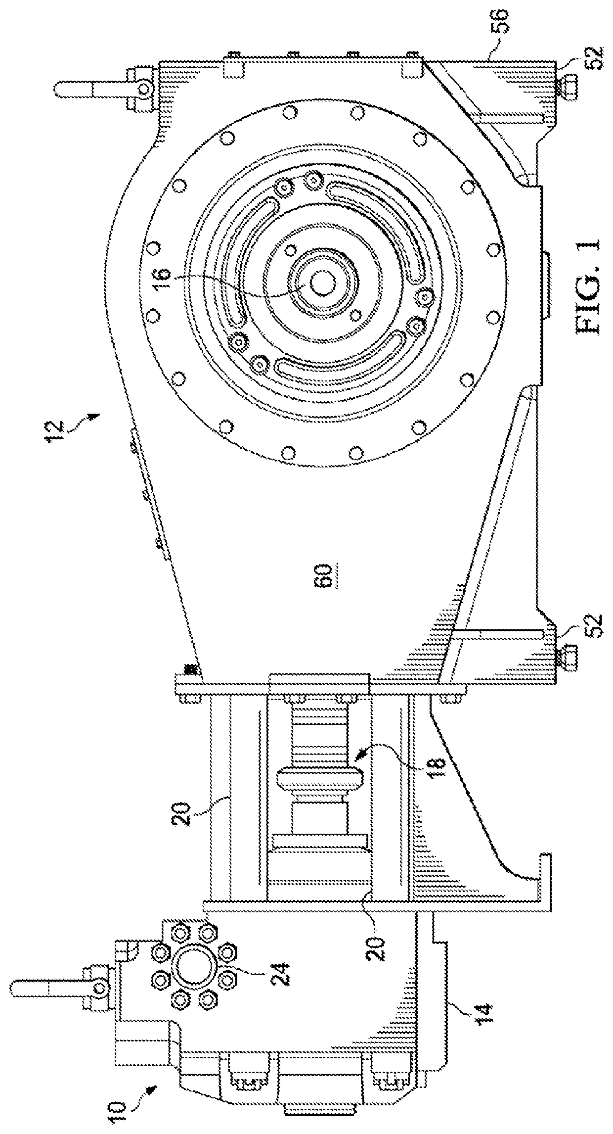
[0076]FIG. 1 is an illustration of a reciprocating pump assembly 10, such as, for example, a reciprocating plunger pump. Reciprocating pumps can be used, for example, as frac pumps, mud pumps, cement pumps, and the like. Terminology may be used in this disclosure that is commonly used in a given pump system; however, unless otherwise stated, this disclosure also includes comparable components of other pump systems (e.g., crossheads and pistons). Referring to FIG. 1, the pump assembly 10 includes a power end housing 12 coupled to a fluid end housing 14 via a plurality of stay rods 20. The power end housing 12 includes a crankshaft 16 depicted, for example, in FIG. 40), which is mechanically connected to a motor (not shown), which in operation, rotates the crankshaft 16 in order to drive the reciprocating pump assembly 10. In particular, rotation of the crankshaft 16 causes a plunger assembly 18 to reciprocate toward and away from the fluid end housing 14, which causes fluid to be pum...


PUM


Abstract

A gearbox is coupled to a power end housing of a reciprocating pump, where the gearbox includes at least one support member having a first end securely affixed to the gearbox, and the at least one support member having a second end securely affixed to an immobile part of the reciprocating pump for supporting the gearbox and resisting movement of the gearbox relative to the reciprocating pump.

Description

CROSS-REFERENCE TO RELATED APPLICATIONS[0001]This application is a continuation application of U.S. application Ser. No. 16 / 723,841 filed on Dec. 20, 2019, which is a continuation of U.S. application Ser. No. 15 / 882,496 filed Jan. 29, 2018, now U.S. Pat. No. 10,520,037, which is a continuation of U.S. application Ser. No. 14 / 808,654 filed Jul. 24, 2015, now U.S. Pat. No. 9,879,659, which claims the benefit of U.S. Provisional Application No. 62 / 155,793 filed May 1, 2015, U.S. Provisional Application No. 62 / 095,689 filed Dec. 22, 2014, and U.S. Provisional Application No. 62 / 029,271 filed Jul. 25, 2014, each of which are incorporated herein by reference in their entireties.TECHNICAL FIELD[0002]This disclosure relates to a reciprocating pump assembly, and in particular, a power end housing for a reciprocating pump assembly.BACKGROUND OF THE DISCLOSURE[0003]In oil field operations, reciprocating pumps are used for various purposes. For example, reciprocating pumps are commonly used for...

Claims


Application Information

Patent Timeline
Patent Type & Authority Applications(United States)
IPC IPC(8): F04B53/22F04B39/12F04B19/22F04B37/00F04B53/16F04B53/00
CPCF04B53/22F04B39/128F04B19/22F16C35/04F04B53/16F04B53/006F04B53/162F04B37/00F04B1/0404F04B1/053F04B9/045F04B53/14F16C9/02F04B9/02F16C19/26F16C19/466F16C35/067F16C43/04F16C2360/42F16C7/023F04B7/0069F04B2201/06B21K1/26
Inventor BYRNE, JOSEPH H.KOTAPISH, EDWARD C.BAYYOUK, JACOB A.WAWERU, LAWRENCE
Owner SPM OIL & GAS INC
Why Eureka
Try Eureka