Shaft Driving Tool

Active Publication Date: 2021-09-09
BLASI ROBERT A +1
View PDF2 Cites 2 Cited by
  • Summary
  • Abstract
  • Description
  • Claims
  • Application Information

AI Technical Summary

Benefits of technology

This patent describes a tool used for removing gears from an axle. The tool has a member that holds the apertured member in place, either beneath the screw's shaft or engaged with the gear to be pulled off. The tool can be easily attached to the fan using set screws. The technical effect is that this tool simplifies the process of removing gears from fans and allows for easier attachment to the fan.

Problems solved by technology

Commonly constructed and configured jack screw actuated gear pullers and shaft driving tools are often mechanically cumbersome and are difficult to operate.
Where such a tool must be operated within a tight locale offering a limited working space, the tool may be virtually impossible to operate.

Method used


Image

  • Shaft Driving Tool
  • Shaft Driving Tool
  • Shaft Driving Tool

Examples


Embodiment Construction

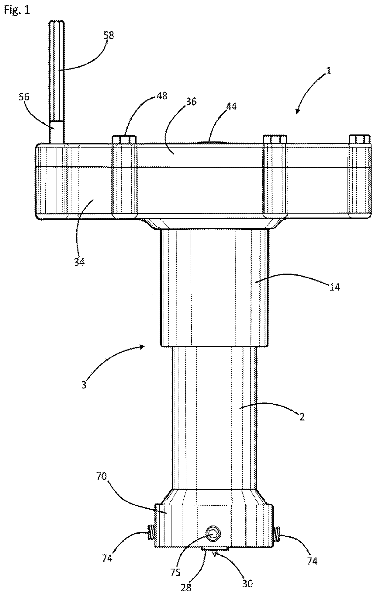
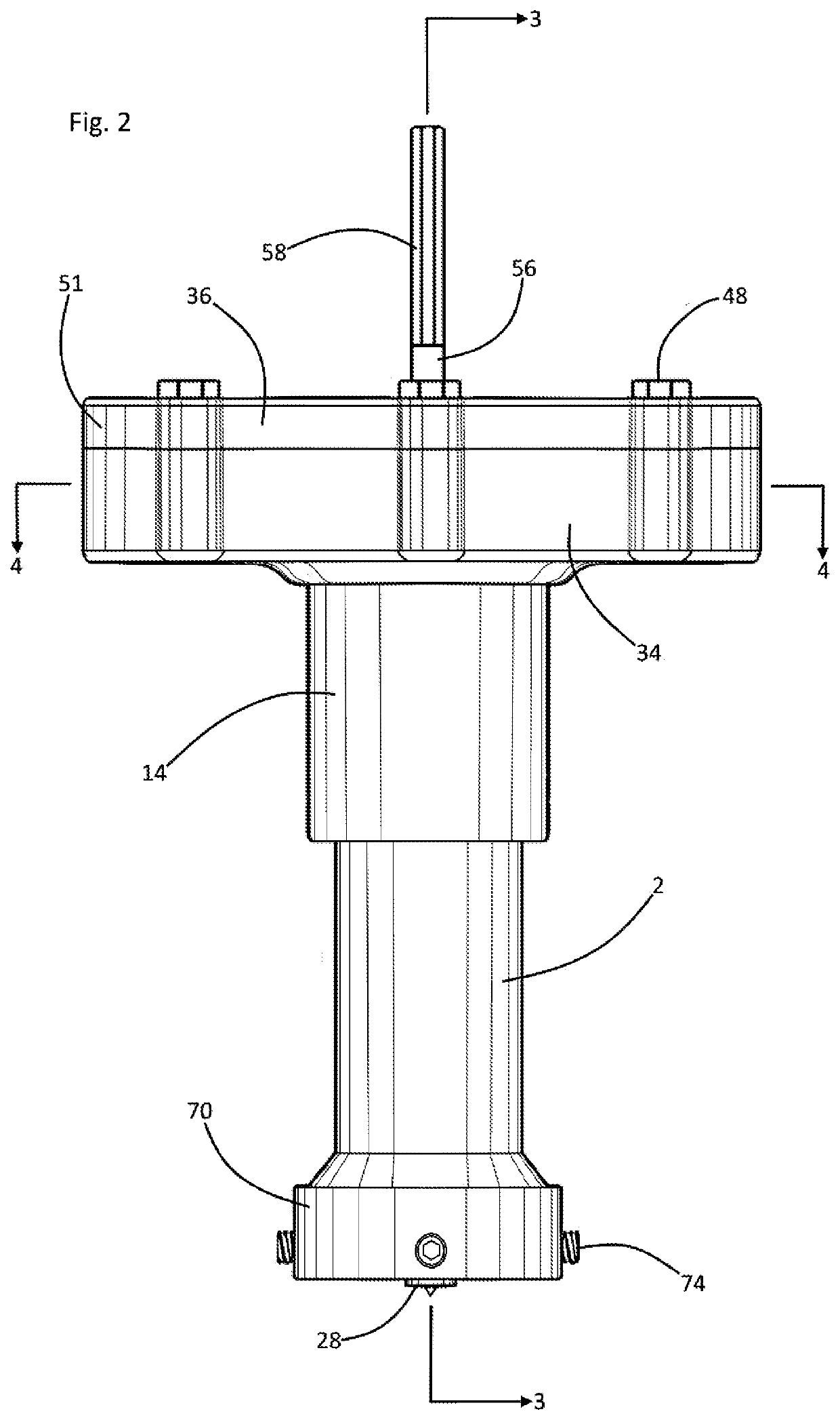
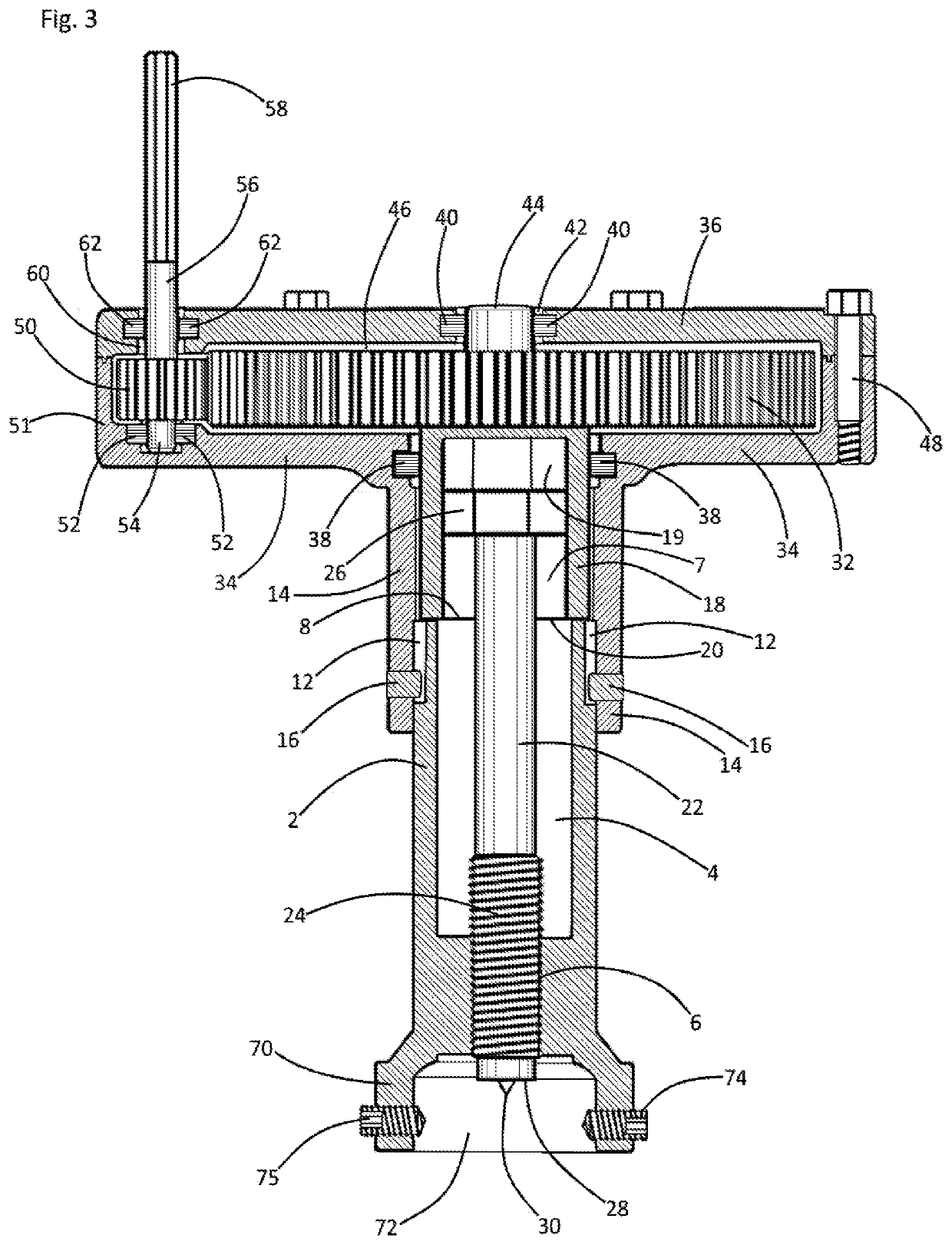
[0029]Referring now to the drawings and in particular to Drawing FIGS. 1-4, a preferred suitable embodiment of the instant inventive tool for driving a shaft is referred to generally by Reference Arrow 1. The tool 1 comprises a multiply segmented sleeve which is referred to generally by Reference Arrow 3, such sleeve 3 comprising a lower segment 2, an upper segment 18, and a medial segment 14.

[0030]The sleeve's lower segment 2 preferably has a vertically extending hollow bore 4 having an upper opening 8. The inner wall of the lower end of such bore 4 preferably presents female helical threads 6. In the FIGS. 1-4 embodiment, the upper end of the sleeve's lower segment 2 presents a pair of vertically extending travel slots 12 which open radially outwardly. Such slots 12 advantageously non-circularly configure the lower segment's upper end to function as a rotation resisting pin half of a first or lower pin-and-socket joint. The sleeve's medial segment 14 is preferably closely fitted f...


PUM


Abstract

A tool for driving a shaft a shaft within an apertured member, the tool incorporating a segmented sleeve having upper, lower, and medial segments, each segment having upper and lower ends, a hollow bore of the lower segment being helically threaded; a shaft biasing screw mounted within the lower segment's hollow bore, ; upper and lower joints, the upper joint connecting the upper end of the screw with the upper segment, and the lower joint connecting the medial segment with the lower segment; a first gear component attached to the upper segment; a support frame attached to the medial segment; a second gear component mounted rotatably upon the support frame, the second gear component being positioned for rotating the first gear component; a rotary power input stem fixedly attached to the second gear component; and a clamp or hook arms adapted for positioning the apertured member beneath the screw's shaft biasing lower end.

Description

[0001]Reference is made to U.S. patent application Ser. No. 17 / 002,544 entitled “Shaft Driving Tool” and filed Aug. 25, 2020. The instant application constitutes a continuation in part of said '544 application. The specification and drawings of the instant application and those of said '544 application are substantially identical with exceptions that the instant application further discloses a drill actuated planetary gear drive assembly as an alternative to the pinion gear and drive gear assembly disclosed in the '544 application. The inventor of and applicants of said '544 application and the instant application are the same, and the instant application is filed prior to any issuance or abandonment of said '544 application. The benefit of and priority from said '544 application is hereby claimed to the extent of said application's disclosure.STATEMENT REGARDING FORMAT OF FILING[0002]The Specification and Abstract which follow constitute a “clean version” of a “line-in / line-out” fo...

Claims


Application Information

Patent Timeline
IPC IPC(8): B25B27/02
CPCB25B27/023F16H1/28B25B27/062B25B27/04
Inventor BLASI, ROBERT A.
Owner BLASI ROBERT A
Why Eureka
Try Eureka