
Radar sensor

Active Publication Date: 2021-09-09
NANYANG TECH UNIV
View PDF0 Cites 2 Cited by
  • Summary
  • Abstract
  • Description
  • Claims
  • Application Information

AI Technical Summary

Benefits of technology

The invention provides systems and methods for a radar sensor that has a larger detectable range, is not affected by phase ambiguity, and can be combined with machine learning techniques for dynamic gesture recognition. These technical effects enhance the performance of the radar sensor and improve its ability to identify and recognize objects.

Problems solved by technology

However, such optical measurement techniques are unable to penetrate dust and fog in harsh environments as the optical diffusion in such environments cause measurement errors to occur.
However, such a technique cannot be used for short-range measurements or high-precision distance detection due to the relatively low accuracy in very short-time interval measurements.
However, in order for FMCW radar to achieve high spatial resolution at short distances, extremely steep frequency ramps are required to drive the radar as the steep frequency ramps allow the system to generate larger frequency shifts between the transmitted signal and the reflected signal.
The trade-off between these two properties results in the generation of a nonlinear output signal which is detrimental to the performance of the radar system.
However, a phase ambiguity issue arises when the distance measured from a target is larger than a single wavelength.
In such a scenario, the phase evaluation technique will produce an ambiguous result due to a periodical repetition over the distance variation as the radar system is unable to distinguish different distances whenever the corresponding phase difference exceeds one wavelength.
In short, the displacement between the radar system and the target can only be measured when the target is within a range of a wavelength of the transmitted signal thereby severely limiting the radar system's range of detection.

Method used


Image

  • Radar sensor
  • Radar sensor
  • Radar sensor

Examples


Embodiment Construction

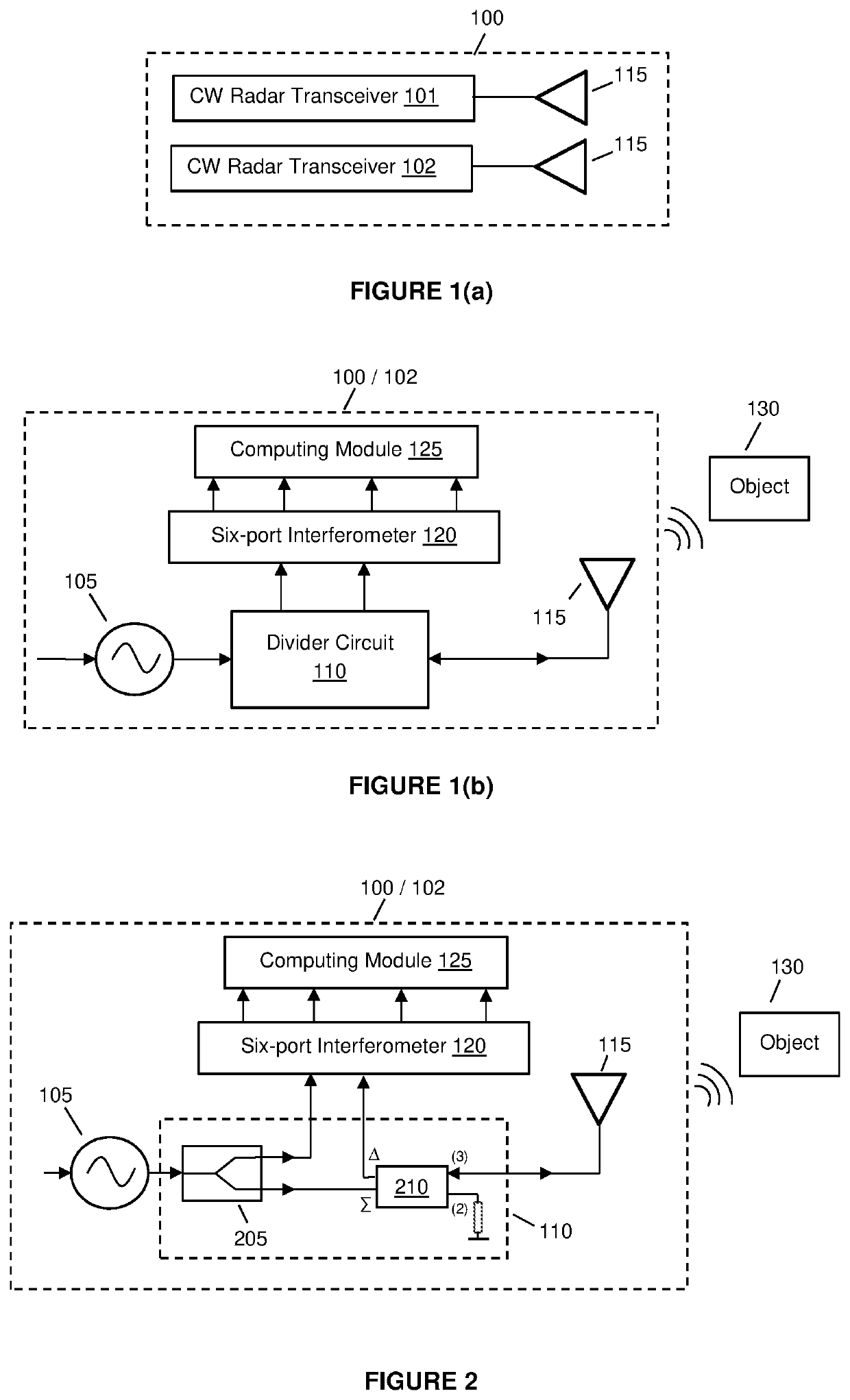
[0066]This invention relates to a radar sensor and a method for using the radar sensor for detecting nearby objects and in embodiments of the invention, the radar sensor may be used for dynamic gesture recognition and one skilled in the art will recognize that the radar sensor may be used for other similar applications without departing from this invention. In particular, the radar sensor comprises a pair of continuous wave (CW) radar transceivers that each has a leaky wave antenna that are provided adjacent to each other.

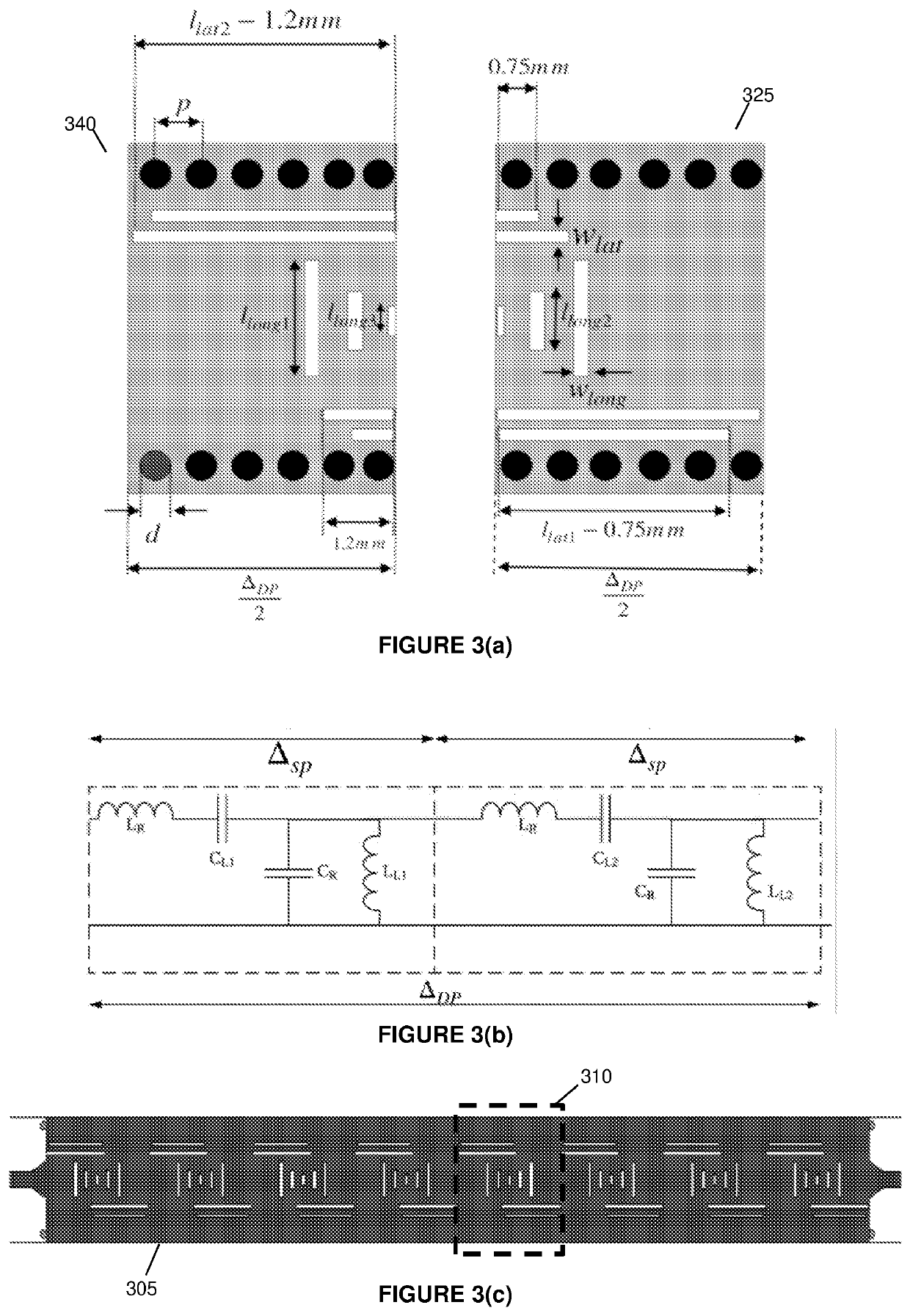
[0067]In a more particular embodiment, each CW radar transceiver in the radar sensor comprises a voltage-controlled oscillator (VCO), a divider circuit, a double periodic composite right / left hand (CRLH) substrate integrated waveguide (SIW) leaky wave antenna, and a six-port interferometer whereby the double periodic CRLH SIW leaky wave antenna of the first CW radar transceiver is positioned adjacent the double periodic CRLH SIW leaky wave antenna of the second CW ...


PUM


Abstract

Example embodiments describe a radar sensor, whereby the radar sensor comprises a pair of continuous wave (CW) radar transceivers that each has a leaky wave antenna that are provided adjacent to each other. Each CW radar transceiver comprises a microwave frequency transmission circuit configured to transmit and receive signals reflected off a nearby object. The transmitted and received signals are then processed by the radar sensor to determine a relative displacement between the detected object and the radar sensor. This determined relative displacement may then be used with machine learning techniques to identify dynamic gestures made within the radar sensor's range of detection.

Description

CROSS-REFERENCE TO RELATED APPLICATION[0001]This application claims the benefit of Singapore Patent Application No. 10201806351Y, entitled “A Microwave Based 3D Sensor for Dynamic Gesture Recognition” and filed on 25 Jul. 2018, which is expressly incorporated by reference herein in its entirety.FIELD OF THE INVENTION[0002]This invention relates to a radar sensor, whereby the radar sensor comprises a pair of continuous wave (CW) radar transceivers that each has a leaky wave antenna that are provided adjacent to each other. In particular, each CW radar transceiver comprises a microwave frequency transmission circuit configured to transmit and receive signals reflected off a nearby object. The transmitted and received signals are then processed by the radar sensor to determine a relative displacement between the detected object and the radar sensor. This determined relative displacement may then be used with machine learning techniques to identify dynamic gestures made within the radar...

Claims


Application Information

Patent Timeline
IPC IPC(8): G01S7/35H01Q13/20G01S7/03G01S13/38G01S13/42
CPCG01S7/354H01Q13/20G01S7/417G01S13/38G01S13/422G01S7/03H01Q3/22H01P5/18H01P1/182H01Q13/28G01S7/023G01S13/88
Inventor CHANDRASEKARAN, KARTHIK THOTHATHRIALPHONES, AROKIASWAMIKARIM, MUHAMMAD FAEYZTHOMAS, ASHITA PRIYA
Owner NANYANG TECH UNIV
Learn More