
Production method for prepreg, prepreg tape, and fiber reinforced composite material, and coating device

a production method and fiber reinforced composite material technology, applied in the direction of coatings, etc., can solve the problems of reducing the mechanical property of frp, reducing the quality of prepreg, and difficult to run reinforcing fiber sheets, etc., to achieve the effect of enhancing the productivity of prepreg, preventing fuzz, and suppressing fuzz

Active Publication Date: 2021-09-23
TORAY IND INC
View PDF5 Cites 0 Cited by
  • Summary
  • Abstract
  • Description
  • Claims
  • Application Information

AI Technical Summary

Benefits of technology

This patent is about a method and apparatus for producing a prepreg. The main technical effects are that it reduces the generation of fuzz, allows for continuous production without clogging, efficiently impregnates the reinforcing fiber sheet with resin, and increases the production speed. Additionally, it can be used to functionalize the prepreg and surface of a CFRP. Overall, the method and apparatus improve the production of prepreg and enhance its quality.

Problems solved by technology

This is considered to be intended to disturb part of the arrangement of the reinforcing fiber bundle so that the matrix resin can flow in, but applying this idea to a reinforcing fiber sheet conceivably causes the reinforcing fiber sheet to be deformed, resulting in not only degrading the quality of the prepreg but also decreasing the mechanical property of FRP.
In addition, if the technology of Patent Literature 2 is applied, abrasion at the web-guide generates fuzz, conceivably making it difficult for the reinforcing fiber sheet to run.
In addition, the method of Patent Literature 3 makes it more likely that fuzz is retained in a liquid pool during continuous production and that the fuzz clogs a pultrusion portion.
There is a problem in that, in particular, running a strip-like reinforcing fiber bundle continuously at a high speed causes the frequency of clogging with fuzz to be very high, and accordingly, enables production to be carried out only at a very low speed and fails to increase productivity.
In addition, a horizontal type pultrusion method makes it necessary to seal the die hermetically to prevent liquid leakage and makes it insufficient to collect fuzz during continuous production.
Because of this, there is a problem in that not only the movement of the bubbles is inhibited by the liquid, but also the impregnation with the matrix resin is inhibited by the bubbles, resulting in low impregnation efficiency.
Furthermore, the Patent Literature also proposes exhausting bubbles through a vent, but the exhaustion takes place only near the outlet of a die, and the effect of the exhaustion is considered to be limitative.
The nozzle can be optimized with a strand or a roving-form object but does not easily cope with a planar shape such as of a reinforcing fiber sheet.
While passing through this nozzle, a reinforcing fiber sheet generates fuzz, which is conceivably more likely to clog a die when brought into the manifold.

Method used


Image

  • Production method for prepreg, prepreg tape, and fiber reinforced composite material, and coating device
  • Production method for prepreg, prepreg tape, and fiber reinforced composite material, and coating device
  • Production method for prepreg, prepreg tape, and fiber reinforced composite material, and coating device

Examples


examples

[0317]

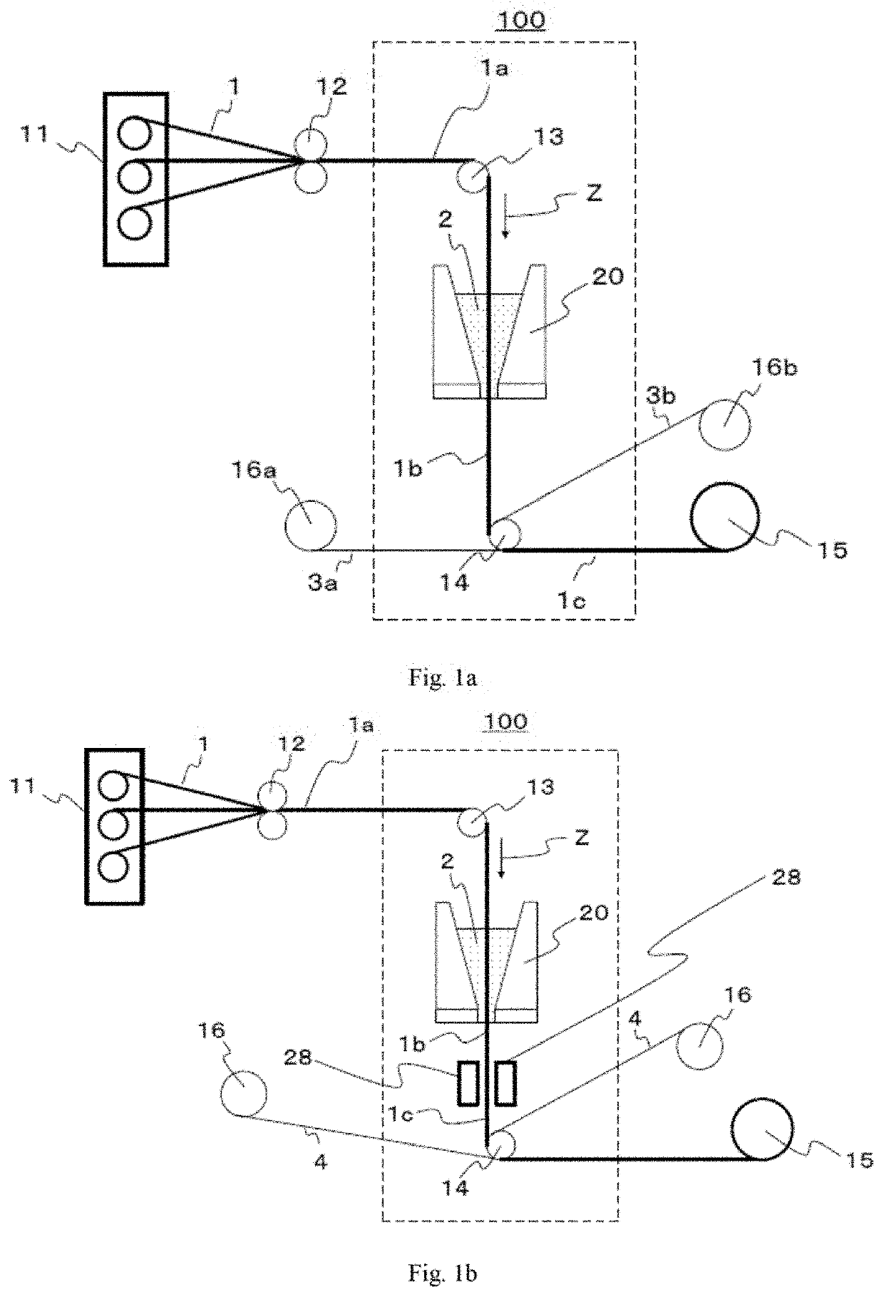
[0318]Unless otherwise specified, a coating section of the type 20c in the form depicted in FIG. 7 was used as a coating section in each of Examples and Comparative Examples, and a device configured by removing a fiber bundle widening device and a smoothing device from a device configured as described in FIG. 15 (here, the depiction of a matrix resin supply device for the coating section is omitted) was used as a prepreg production device. Reinforcing fibers withdrawn from the creels were formed into a reinforcing fiber sheet at the arrangement device 415 disposed above, and the sheet was introduced into the reinforcing fiber preheating device 420.

[0319]

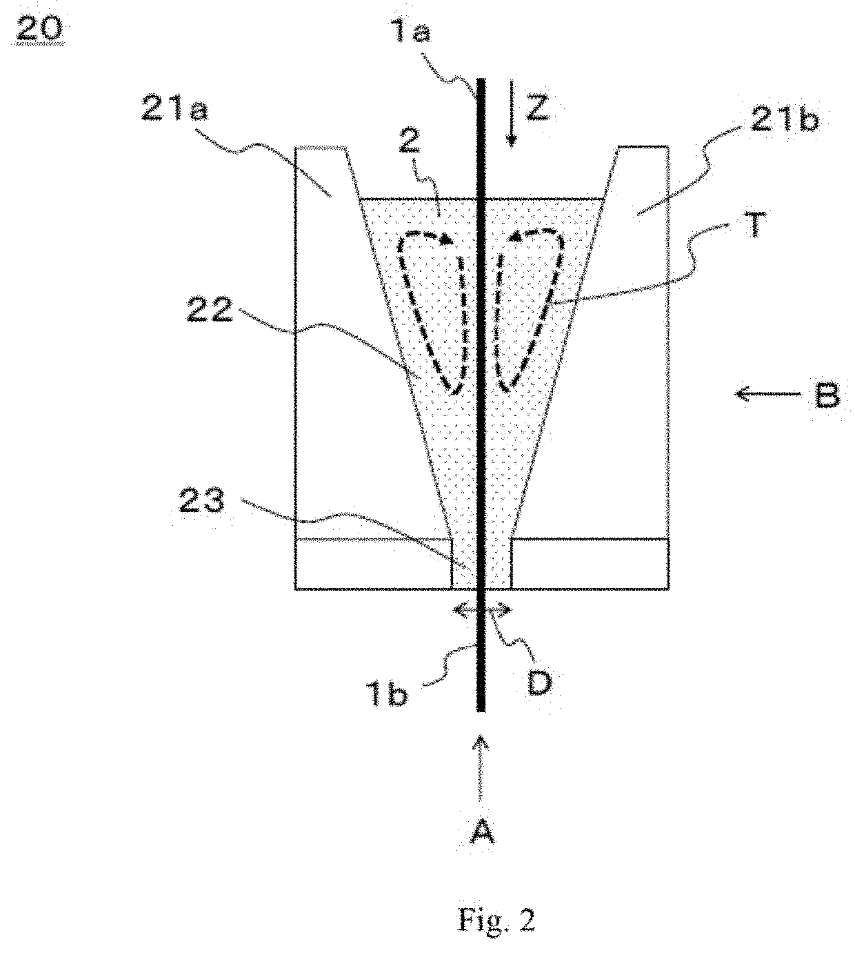
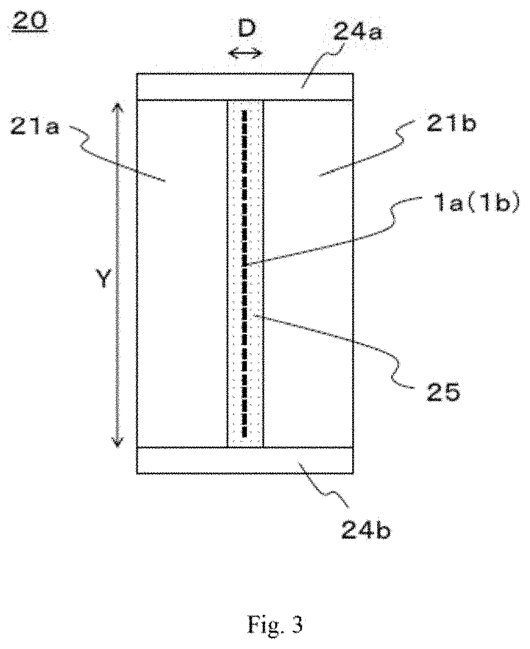
[0320]In the coating section, stainless steel blocks were used as the wall constituent members and forming the liquid pool and the narrowed section, and stainless steel plates were used as the side plate members. Furthermore, to heat the matrix resin, a plate-heater was attached to the periphery of the wall constituent members ...

examples 1 to 4

[0343]A prepreg was produced using a resin film obtained using a thermosetting epoxy resin composition 1 (matrix resin A) in the coating section and using a separately prepared thermosetting epoxy resin composition 2 (matrix resin B) as a resin film. In this Example, however, an additional-impregnation process was not carried out after the application of a resin film. In this regard, the temperature of the matrix resin A in the liquid pool was 90° C. (corresponding to 15 Pa·s). In addition, the running speeds of the reinforcing fiber sheet and the prepreg were 20 m / minute.

[0344]The evaluation results of the running stability of the primary impregnate prepreg in the coating section are shown in Table 1, wherein the relationship L2−W between the width L2 in the lower end portion of the width regulation mechanism and the width W of the primary impregnate prepreg and the height H along which the cross-sectional area of the coating section decreases continuously are changed variously. Th...

example 5

[0346]Application of a matrix resin, simplified additional-impregnation, and application of a resin film were carried out under the same conditions as in Example 1, and then, the prepreg was further introduced into the additional-impregnation device to undergo an additional-impregnation process. The water absorption rate of the prepreg was checked, and found to be 5%, which is a sufficient degree of impregnation.

[0347]Next, the obtained prepregs were laminated in six layers, and cured using an autoclave at 180° C. at 6 kgf / cm2 (0.588 MPa) for two hours to obtain CFRPs. All the obtained CFRPs had a tensile strength of 3.0 GPa, and had suitable mechanical properties as a structural material for the aerospace. In this regard, the tensile strength of the CFRP was measured in the same manner as in WO2011 / 118106, and the value resulting from normalizing the volume % of the reinforcing fibers in the prepreg to 56.5% was used.

[0348]In addition, observing the cross-section of the obtained CF...


PUM

PropertyMeasurementUnit
Lengthaaaaaaaaaa
Lengthaaaaaaaaaa
Heightaaaaaaaaaa

Abstract

A method of producing a prepreg is described, in which a matrix resin is applied to a reinforcing fiber sheet in which the sheet can continuously run without clogging due to generated fuzz even at a high running speed and where the reinforcing fiber sheet can be efficiently impregnated with the matrix resin. A method of producing a prepreg includes allowing a reinforcing fiber sheet to pass substantially vertically downward through the inside of a coating section storing a matrix resin to apply the matrix resin to the reinforcing fiber sheet; and then applying a resin film to a primary impregnate prepreg withdrawn from the coating section.

Description

CROSS REFERENCE TO RELATED APPLICATIONS[0001]This is the U.S. National Phase application of PCT / JP2019 / 032492, filed Aug. 20, 2019, which claims priority to Japanese Patent Application No. 2018-155072, filed Aug. 22, 2018, and Japanese Patent Application No. 2018-170400, filed Sep. 12, 2018, the disclosures of each of these applications being incorporated herein by reference in their entireties for all purposes.FIELD OF THE INVENTION[0002]The present invention relates to a method of producing a prepreg, and particularly relates to a method of impregnating a reinforcing fiber sheet with a matrix resin uniformly.BACKGROUND OF THE INVENTION[0003]Fiber reinforced composite materials (FRP) in which a matrix resin containing a thermoplastic resin or a thermosetting resin is reinforced with a reinforcing fiber are used in various fields such as aerospace materials, automobile materials, industrial materials, pressure vessels, construction materials, housings, medical applications, and spor...

Claims


Application Information

Patent Timeline
IPC IPC(8): C08J5/24B29B15/12B29C70/20B29C70/50C08J7/06
CPCC08J5/24B29B15/125C08J7/06B29C70/50B29C70/20
Inventor OCHI, TAKASHINISHINO, SOAOKI, JUNICHIKONO, YOSHIKAZUSUZUKI, TAMOTSUIKUSHIMA, TAKASHI
Owner TORAY IND INC
Learn More