
Fastener and method of installation

a technology of fasteners and screws, applied in the field of stud-type fasteners, can solve the problems of affecting affecting the patient's comfort, so as to reduce patient discomfort and anxiety, and improve the overall interval of time. the effect of reducing the overall interval of tim

Inactive Publication Date: 2021-09-30
REMO MICHAEL
View PDF8 Cites 0 Cited by
  • Summary
  • Abstract
  • Description
  • Claims
  • Application Information

AI Technical Summary

Benefits of technology

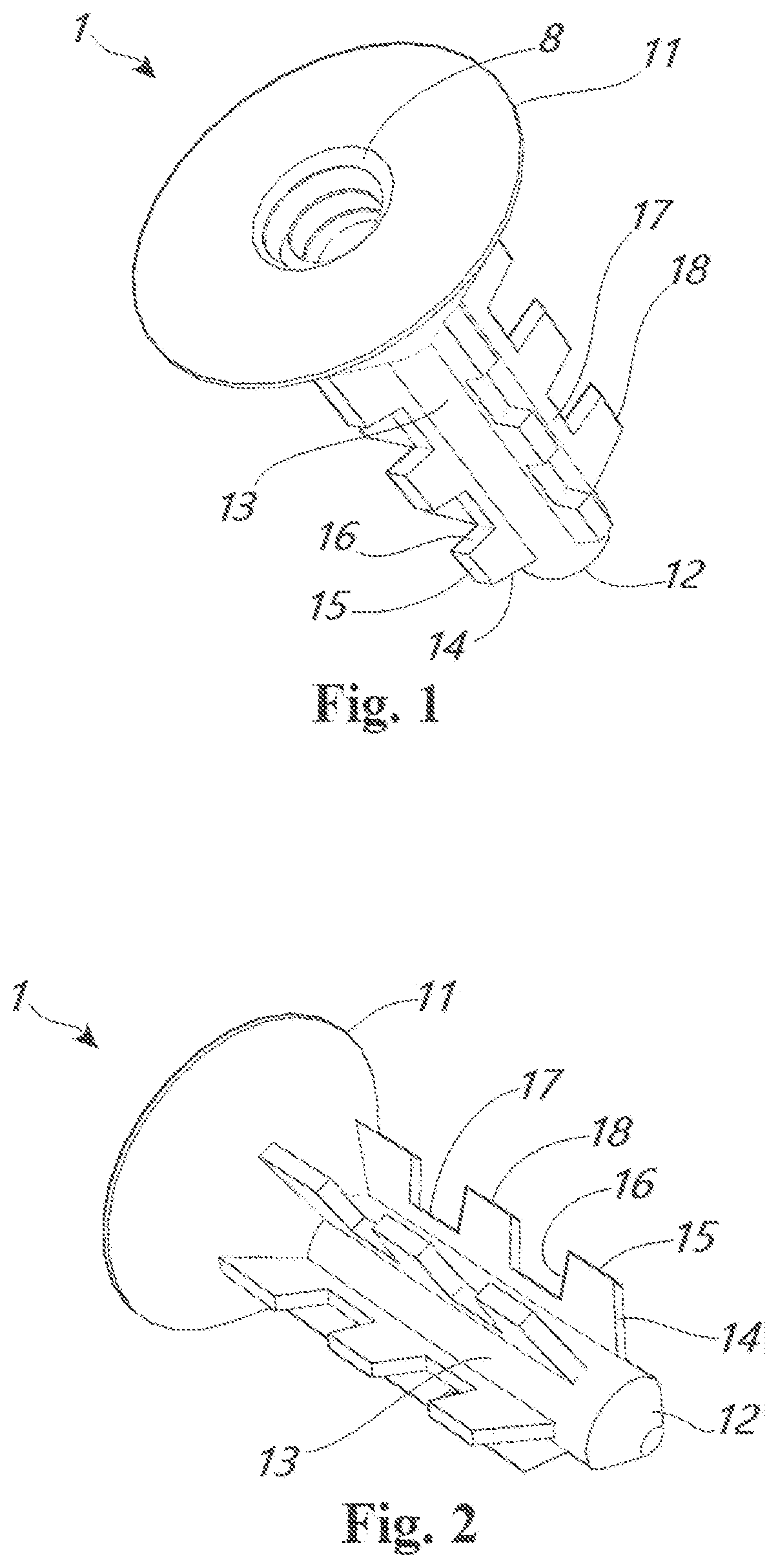
The invention aims to provide a fastener for medical or dental use that requires minimal preparation of a site in bone. The fastener can be installed into a bone immediately after only modest initial preparation of a site, reducing or eliminating intermediate preparation steps. The fastener has grippable features that allow it to engage with new bone tissue and begin its full-load, intended service role as soon as possible after installation. This shortens patient discomfort and anxiety by decreasing the time between the decision being made to install an implanted fastener for a prosthetic and the final, stable condition of living with an installed prosthetic. The invention also eliminates intermediate visits to a dental clinic for intermediate stages of assembly steps, assessments, or adjustments as part of a long drawn out process for restoring the function of a strong tooth in its proper place, reducing patient costs.

Problems solved by technology

Cadaver bones from other bodies may not be accepted by the patient's body as compatible with itself, and rejection or other immune responses require subsequent expensive treatments and further attempts at reconstructing the tooth, and may also provoke inflammation, pain, and other undesirable conditions.
Although the medical community has spent many years attempting to adjust and refine drilling techniques to overcome lack of bone regrowth onto the implant, even with the drilling techniques of current practice, installing a drilled implant requires many weeks or months.
These various preparatory steps cause unnecessary pain, delay, procedural cost, discomfort, foreboding, and worry on the part of a patient requiring a fastener implant.

Method used


Image

  • Fastener and method of installation
  • Fastener and method of installation
  • Fastener and method of installation

Examples


Embodiment Construction

[0019]While various aspects and features of certain embodiments have been summarized above, the following detailed description illustrates a few exemplary embodiments in further detail to enable one skilled in the art to practice such embodiments. The described examples are provided for illustrative purposes and are not intended to limit the scope of the invention.

[0020]In the following description, for the purposes of explanation, numerous specific details are set forth in order to provide a thorough understanding of the described embodiments. It will be apparent to one skilled in the art, however, that other embodiments of the present invention may be practiced without some of these specific details. Several embodiments are described herein, and while various features are ascribed to different embodiments, it should be appreciated that the features described with respect to one embodiment may be incorporated with other embodiments as well. By the same token, however, no single fea...


PUM


Abstract

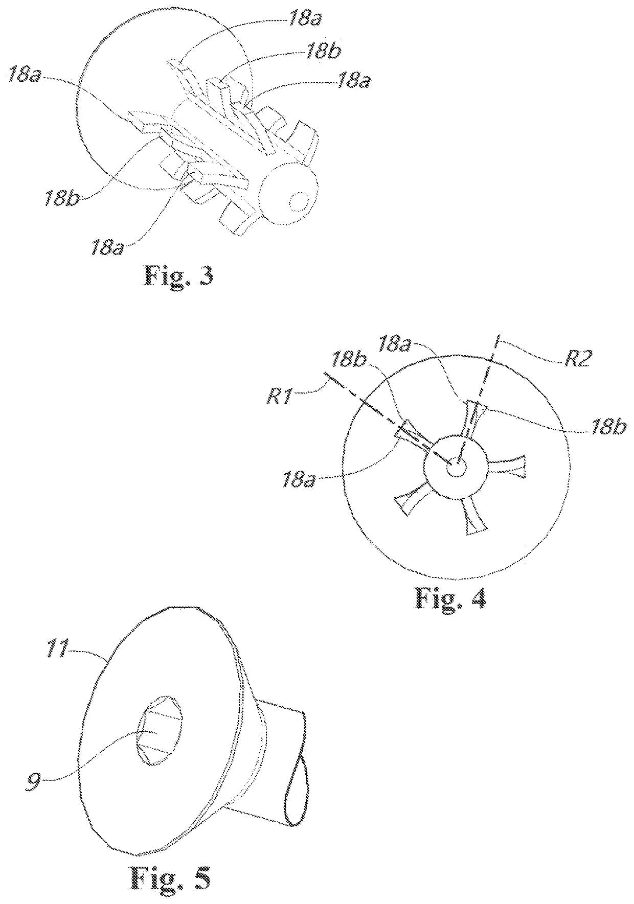
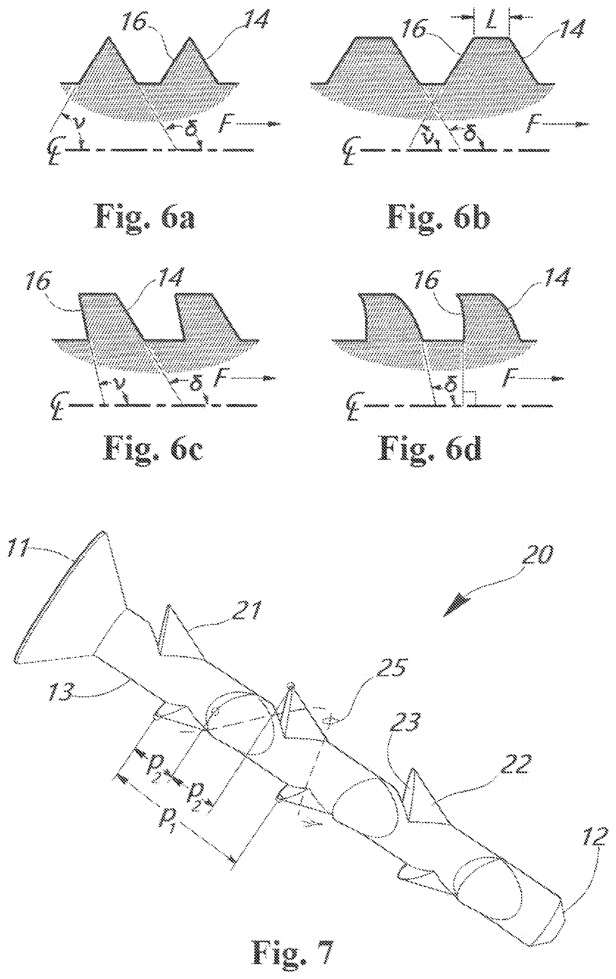
The invention is a fastener for medical or dental use which requires minimal preparation of a site in bone. According to one embodiment the fastener includes a shank and a head having an aperture with a torque-receiving aperture such as a threaded hole or a polygon such as a hex-sided hole. The other end of the shank is a blunt or a sharp point. Another embodiment includes a radially spaced apart series of strakes each having a linearly spaced apart series of barbs. An alternative embodiment includes on the shank a radially spaced apart series of linear arrays of barbs emerging from the shank itself. The linear spacings may be staggered from one radial line to the next so that as a whole the barbs are arranged into one or more continuous helicies.

Description

COPYRIGHT STATEMENT[0001]A portion of the disclosure of this patent document contains material that is subject to copyright protection. The copyright owner has no objection to the facsimile reproduction by anyone of the patent document or the patent disclosure as it appears in the Patent and Trademark Office patent file or records, but otherwise reserves all copyright rights whatsoever.CROSS REFERENCE TO RELATED APPLICATION[0002]This non-provisional utility application claims the benefit of and priority to U.S. provisional application Ser. 63 / 003,175 “Fastener,” filed 31 Mar. 2020. The entire contents of U.S. provisional application Ser. 63 / 003,175 “Fastener,” filed 31 Mar. 2020 is hereby incorporated into this document by reference.FIELD[0003]The invention relates to a stud type fastener designed to be driven into a substrate material with minimal advance preparation of the substrate material.BACKGROUND[0004]Some fasteners for cancellous or fibrous materials require advance prepara...

Claims


Application Information

Patent Timeline
Patent Type & Authority Applications(United States)
IPC IPC(8): A61C8/00
CPCA61C8/0028A61C2008/0046A61C8/0037A61C8/0019
Inventor REMO, MICHAEL
Owner REMO MICHAEL
Learn More