Cooling apparatus

a cooling apparatus and cooling fluid technology, applied in the field of cooling apparatus, can solve the problems of high installation cost, large temperature deviation in the width direction of hot-rolled steel sheet, and complicated installation of the whole apparatus, so as to reduce the initial flow of cooling fluid and improve the cooling quality

Inactive Publication Date: 2021-09-30
POHANG IRON & STEEL CO LTD
View PDF0 Cites 0 Cited by
  • Summary
  • Abstract
  • Description
  • Claims
  • Application Information

AI Technical Summary

Benefits of technology

[0028]The cooling apparatus in the present disclosure has an advantage of reducing an initial flow of a cooling fluid flowing into a chamber member.
[0029]As a result, it is possible to prevent the cooling fluid from being distributed in a biased manner and to prevent the cooling fluid discharged through a discharge member from being discharged in a biased manner.
[0030]Therefore, a body to be cooled such as a steel sheet, or the like, cooled by the cooling fluid discharged through the discharge member may be uniformly cooled, such that the cooling quality may be improved.

Problems solved by technology

Therefore, the turbulent cooler has a disadvantage in that it may make the entire installation complicated and requires high installation costs, since a supplementary apparatus forming pressure is required.
In addition, since the speed of the cooling water sprayed through the nozzle is very fast, the flow of cooling the steel sheet may be very unstable.
Therefore, when a hot-rolled steel sheet is cooled using a turbulent cooler, a large temperature deviation in a width direction of the hot-rolled steel sheet occurs.
However, the spray cooler has a very small amount of cooling water discharged per unit time, such that the hot-rolled steel sheet may not be cooled rapidly, and the cooling efficiency may be also lowered.
That is, a problem of supplying water in a biased manner, in which cooling water is not discharged from the discharge member 200′ coupled to one end portion side of the chamber member 100′ and cooling water is only discharged from the discharge member 200′ coupled to the other end portion side of the chamber member 100′may occur.
Accordingly, it may cause a serious problem of deterioration of the quality of the steel sheet due to unbalanced cooling of the steel sheet.

Method used


Image

  • Cooling apparatus
  • Cooling apparatus
  • Cooling apparatus

Examples


Embodiment Construction

[0040]Hereinafter, specific embodiments of the present disclosure will be described in detail with reference to the accompanying drawings. It will be apparent to those skilled in the art that modifications and variations could be made without departing from the scope of the present disclosure, as defined by the appended claims.

[0041]In addition, the same reference numerals will be used throughout the drawings for elements having the same or similar functions and operations.

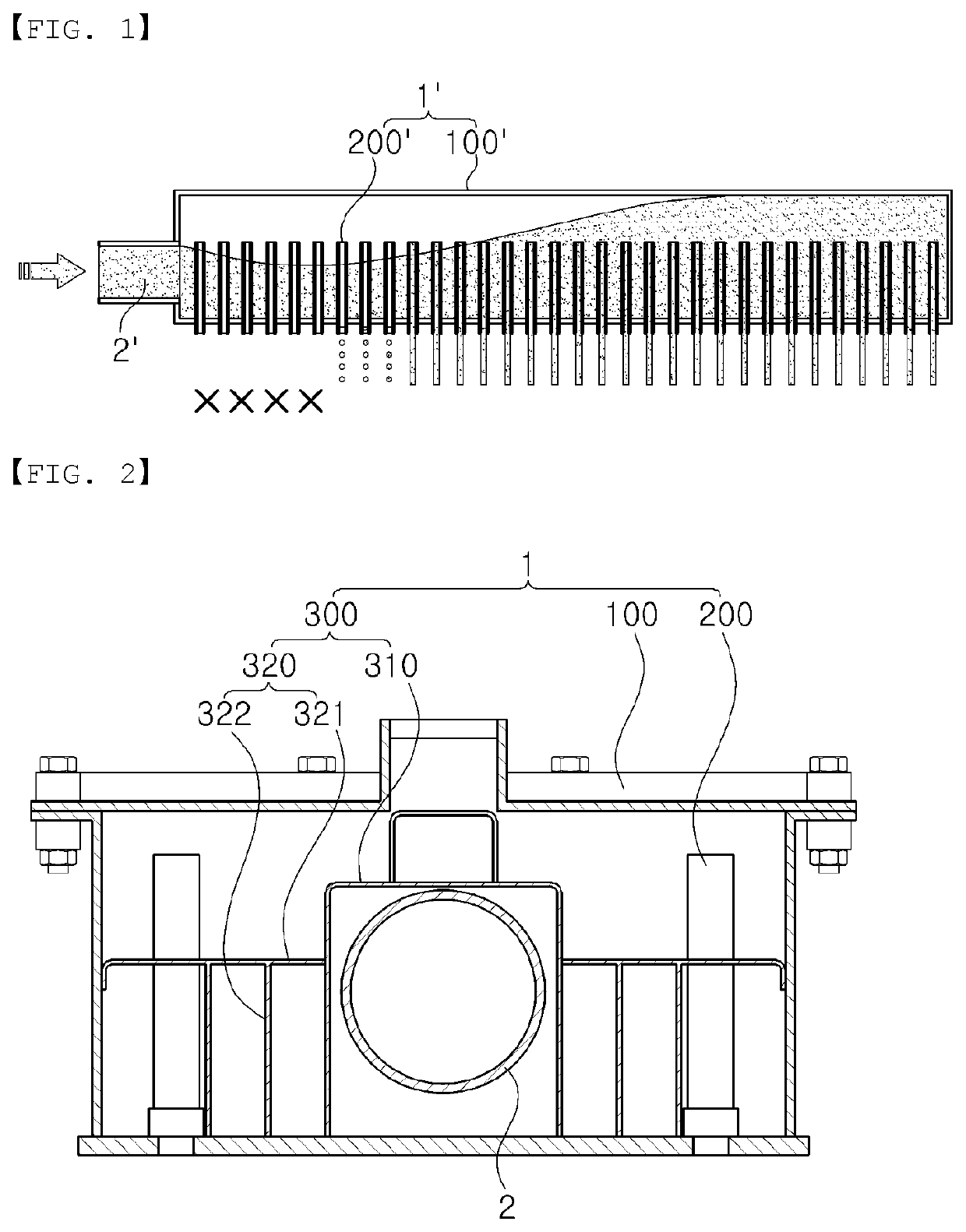
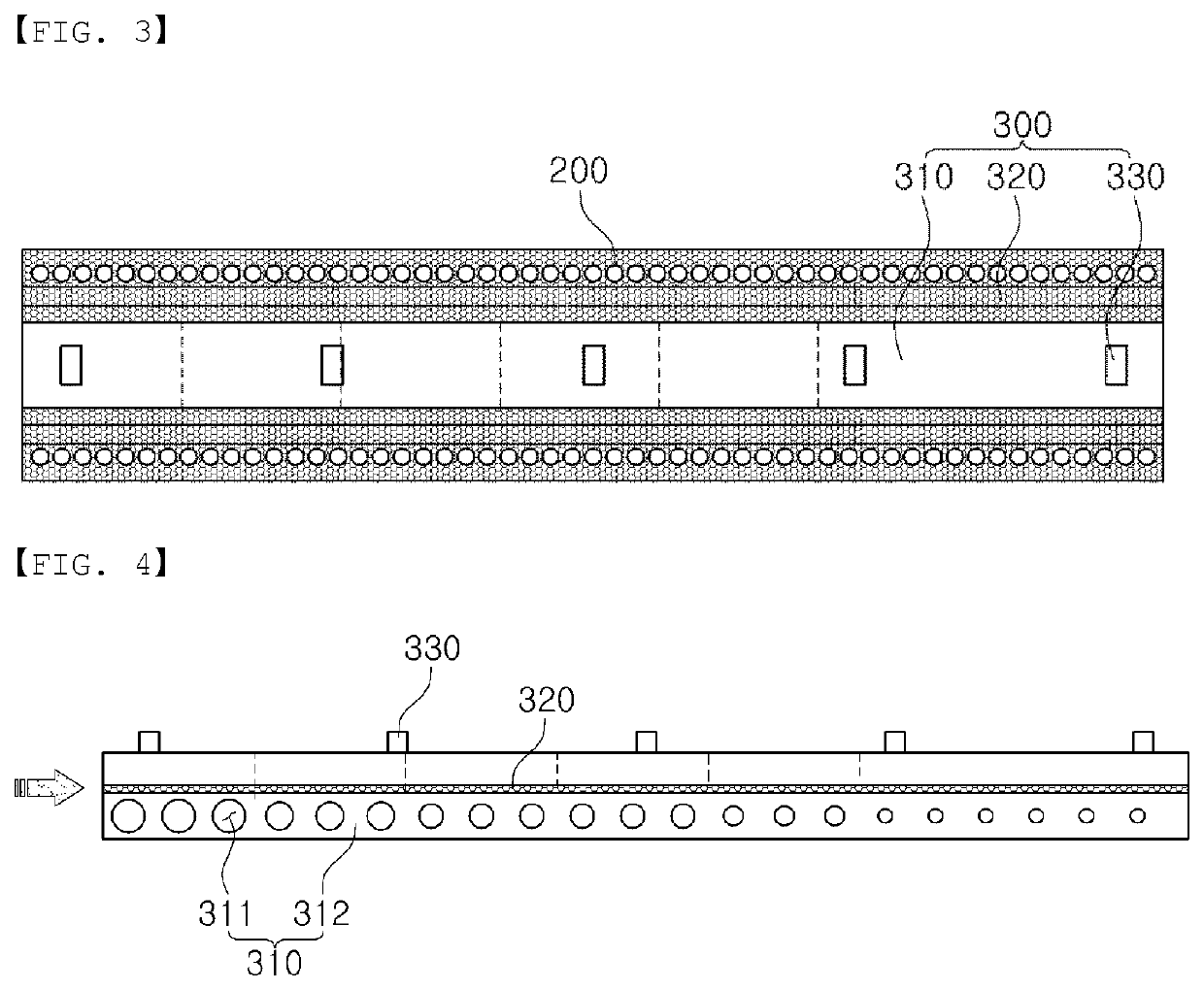
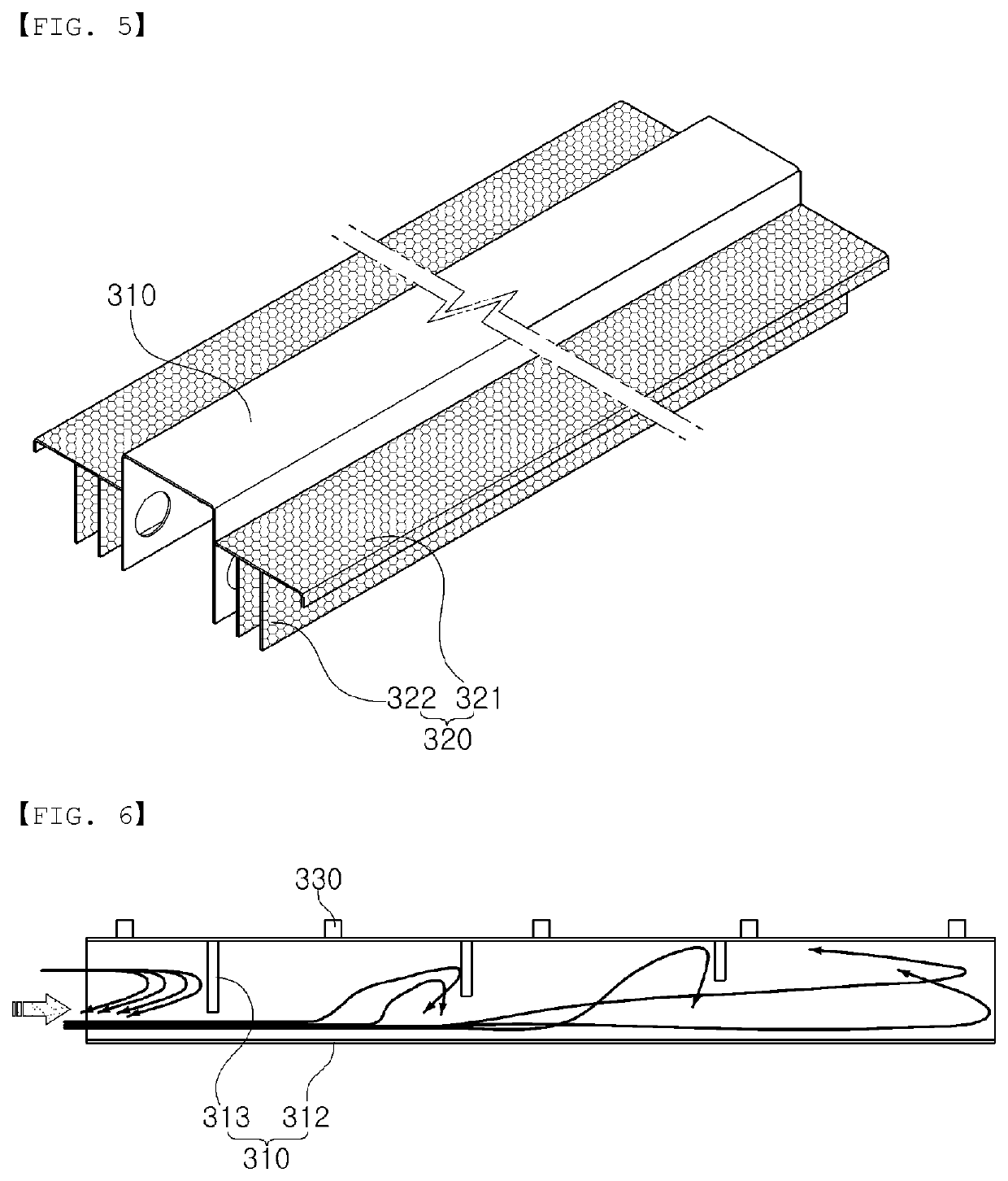
[0042]The present disclosure relates to a cooling apparatus 1 performing cooling for a body to be cooled such as a hot-rolled steel sheet, and the like, which may reduce an initial flow of a cooling fluid flowing into a chamber member 100. As a result, the cooling fluid inside the chamber member 100 may be prevented from being distributed in a biased manner, such that the cooling fluid discharged through a discharge member 200 may be prevented from being discharged in a biased manner.

[0043]Therefore, a body to be ...


PUM

PropertyMeasurementUnit
resistanceaaaaaaaaaa
internal resistanceaaaaaaaaaa
widthaaaaaaaaaa

Abstract

A cooling apparatus according to an embodiment of the present invention may comprise: a chamber member to which a cooling fluid is supplied from the outside; a discharge member, provided in the chamber member, for discharging the cooling fluid inside the chamber unit; and a resistance member, provided in an inlet portion of the chamber member, for inhibiting an initial flow of the cooling fluid supplied into the chamber member.

Description

TECHNICAL FIELD[0001]The present disclosure relates to a cooling apparatus performing cooling for a body, such as a hot-rolled steel sheet, or the like, to be cooled.BACKGROUND ART[0002]A steel sheet passing through a rolling mill is cooled on a run out table. Cooling is mainly performed by using cooling water and using a method of spraying the cooling water through a nozzle.[0003]Among cooling methods, coolers spraying the cooling water through the nozzle may be divided into a turbulent cooler, a spray cooler, and a laminar cooler, depending on types of spraying of the cooling water.[0004]A turbulent cooler sprays cooling water onto the steel sheet by applying a large amount of pressure to an interior. Therefore, the turbulent cooler has a disadvantage in that it may make the entire installation complicated and requires high installation costs, since a supplementary apparatus forming pressure is required.[0005]In addition, since the speed of the cooling water sprayed through the no...

Claims


Application Information

Patent Timeline
Patent Type & Authority Applications(United States)
IPC IPC(8): B21B45/02C21D1/667C21D9/46C21D1/60
CPCB21B45/0233C21D1/60C21D9/46C21D1/667B21B45/0218C21D1/62C21D9/5735C21D9/00F27D15/0206C21D9/0062
Inventor KANG, JONG-HOONMIN, GWAN-SIKKWON, HUI-SEOP
Owner POHANG IRON & STEEL CO LTD
Why Eureka
Try Eureka