Thermostatic flow control device and method of use

a flow control and flow control technology, applied in the field of thermostatic flow control devices, can solve the problems of a large amount of work and achieve the effect of increasing fluid flow and reducing fluid flow

Inactive Publication Date: 2016-08-25
GENERAL ELECTRIC TECH GMBH
View PDF8 Cites 0 Cited by
  • Summary
  • Abstract
  • Description
  • Claims
  • Application Information

AI Technical Summary

Benefits of technology

[0008]As noted above, a valve assembly configured to automatically reset is desirable. Such is true of the subject flow control device. The subject flow control device provides a reliable, temperature-actuated valve assembly having relatively few components, configured to accommodate increases in fluid flow and decreases in fluid flow based on fluid temperature. A method of using the subject flow control device comprises providing at least one, at least partially, thermostatic housing sized, dimensioned and secured within a pipe or circuit used for fluid flow, positioning a center plug member sized and dimensioned for leak minimizing fit within interior area(s) of the housing(s) thereby covering, closing, or obscuring at least one opening defined by at least one wall of the center plug member, and contacting the housing(s) and center plug member with a fluid flow through the pipe or circuit having a temperature greater than the temperature of the flow control device, thereby heating the flow control device causing thermostatic portions of the housing(s) to expand for displacement of the housing wall(s) to expose or further expose the at least one opening in the at least one wall of center plug member for increased fluid flow therethrough. Another method of using the subject flow control device comprises providing at least one, at least partially thermostatic, housing sized, dimensioned and secured within a pipe or circuit used for fluid flow, positioning a center plug member sized and dimensioned for leak minimizing fit within interior area(s) of the housing(s) thereby exposing or further exposing at least one opening defined by the at least one wall of the center plug member, and contacting the housing(s) and center plug member with a fluid flow through the pipe or circuit having a temperature less than the temperature of the flow control device, thereby cooling the flow control device causing the thermostatic portions of the housing(s) to contract for displacement of the housing wall(s) to obscure or further obscure the at least one opening in the at least one wall of the center plug member to minimize or decrease fluid flow therethrough. Still another method of using the subject flow control device comprises providing at least one, at least a partially thermostatic, housing sized, dimensioned and secured within a pipe or circuit used for fluid flow, positioning a center plug member sized and dimensioned for leak minimizing fit within interior area(s) of the housing(s) thereby covering, closing, or obscuring at least one opening defined by at least one wall of the center plug member, and contacting the housing(s) and center plug member with a fluid flow through the circuit having a temperature greater than the temperature of the flow control device, thereby heating the flow control device causing thermostatic portions of the housing(s) to expand for displacement of the housing wall(s) to expose or further expose the at least one opening in the at least one wall of the center plug member for increased fluid flow therethrough, or contacting the housing(s) and center plug member with a fluid flow through the pipe or circuit having a temperature less than the temperature of the flow control device, thereby cooling the flow control device causing thermostatic portions of the housing(s) to contract for displacement of the housing wall(s) to obscure or further obscure the at least one opening in the at least one wall of the center plug member to minimize or decrease fluid flow therethrough.

Problems solved by technology

Likewise, a power plant operating under peak load conditions during peak hours of demand requires a relatively large amount of working fluid that flows through the system contacting the subject flow control device.

Method used


Image

  • Thermostatic flow control device and method of use
  • Thermostatic flow control device and method of use
  • Thermostatic flow control device and method of use

Examples


Embodiment Construction

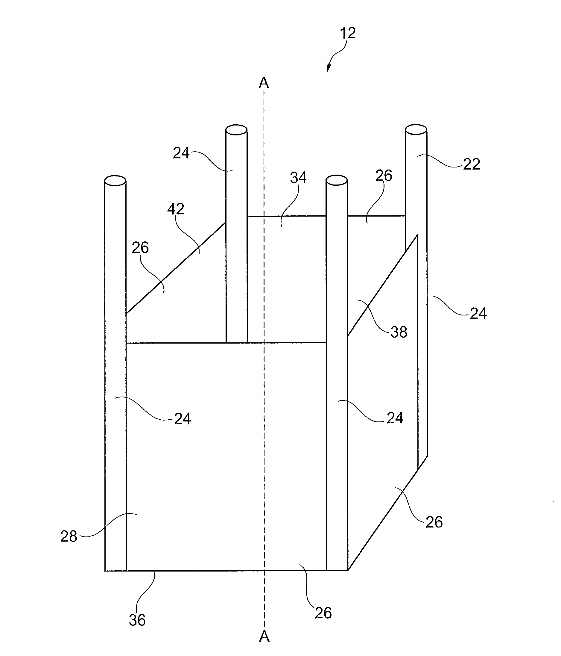
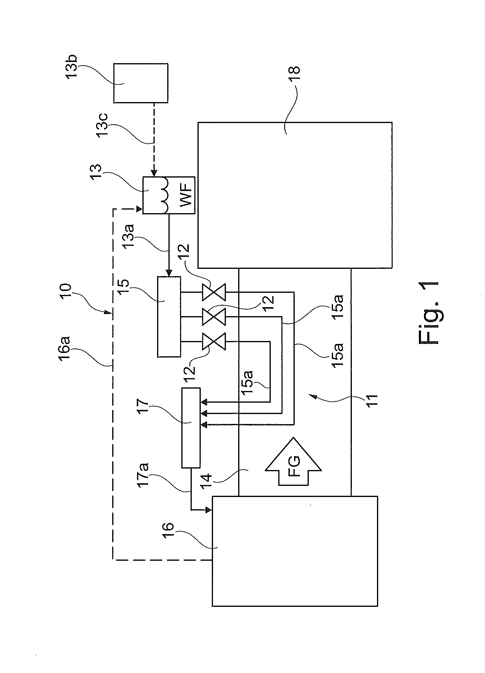
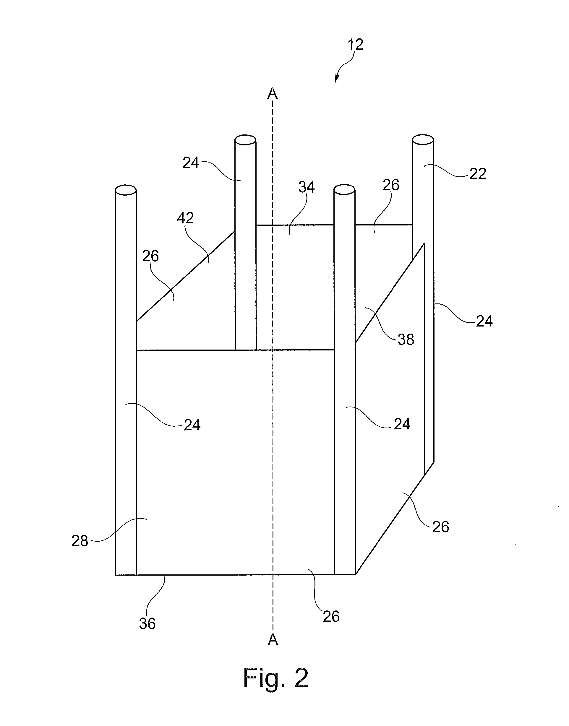
[0025]In the subject exemplifying embodiment, the subject flow control devices 12 such as those illustrated in FIG. 1, are suitably sized and dimensioned for arrangement within pipes 15a of a working fluid circuit 11 for working fluid WF flow. At least a portion of working fluid circuit 11 passes through flue gas FG conduit 14 of an industrial plant 10. Industrial plant 10 may be for example a power plant, such as a coal-, biomass material- or natural gas-fired power plant. In industrial plant 10, the subject flow control device 12 is used to effectively control flow of a working fluid WF, such as water, from an upstream source such as a turbine 13b to a downstream destination such as a boiler 16. Further, flue gas FG is generated in a boiler 16, flows through a fluidly connected conduit 14 to a fluidly connected environmental control system 18. Working fluid WF flowing through working fluid circuit 11 flows through fluidly connected pipe 13a from a working fluid source 13, which ma...


PUM


Abstract

A flow control device is used to regulate fluid flow from an upstream supply source to a downstream destination within a plant. At least portions of the flow control device are fabricated from one or more thermostatic materials selected based on the specific thermostatic properties thereof. The basic arrangement of the flow control device includes at least one housing with at least one thermostatic beam and at least one wall fixed thereto to define a void interior area with opposed open ends, and a center plug member with at least one opening in at least one wall thereof arranged within the interior area for temperature dependent fluid flow therethrough.

Description

FIELD OF THE DISCLOSURE[0001]In general, the present disclosure relates to a thermostatic flow control device and method of using the same for control of a fluid flow. More specifically, the present disclosure relates to a thermostatic flow control device useful in processes where fluid flow requirements are dependent upon changes in plant load and / or thermal conditions.BACKGROUND OF THE DISCLOSURE[0002]Temperature-actuated valve assembles that open or close at a predetermined temperature are used in a wide variety of industries. In the avionics industry, temperature-actuated valve assemblies are commonly used as over-temperature shutoff valves in airplane bleed air systems. Such over-temperature shutoff valves are configured to close to thereby protect temperature sensitive downstream components, when fluid conducted by the valve assembly becomes too hot. Some over-temperature shutoff valves of this type employ thermal fuse plugs made of eutectic alloys that abruptly melt at a pred...

Claims


Application Information

Patent Timeline
Patent Type & Authority Applications(United States)
IPC IPC(8): F16K31/00G05D23/02
CPCF16K31/002F16T1/00G05D23/022F16K3/314F16K25/005F16K27/00F01K5/00
Inventor MAGEE, JEFFREY FRED
Owner GENERAL ELECTRIC TECH GMBH
Why Eureka
Try Eureka