Check patentability & draft patents in minutes with Patsnap Eureka AI!

Target object recognition device, manipulator, and mobile robot

a technology of target object and recognition device, which is applied in image enhancement, image analysis, and program-controlled manipulators, etc., can solve the problem that robots cannot pick up the respective workpieces

Pending Publication Date: 2021-09-30
ORMON CORP
View PDF2 Cites 4 Cited by
  • Summary
  • Abstract
  • Description
  • Claims
  • Application Information

AI Technical Summary

Benefits of technology

The patent allows for the recognition of the state of multiple objects in a specific space.

Problems solved by technology

On the other hand, when positions at which a plurality of workpieces are arranged are misaligned or when a plurality of loaded workpieces collapses and is put into a bulk state, the robot cannot pick the respective workpieces.

Method used


Image

  • Target object recognition device, manipulator, and mobile robot
  • Target object recognition device, manipulator, and mobile robot
  • Target object recognition device, manipulator, and mobile robot

Examples


application example

§ 1 Application Example

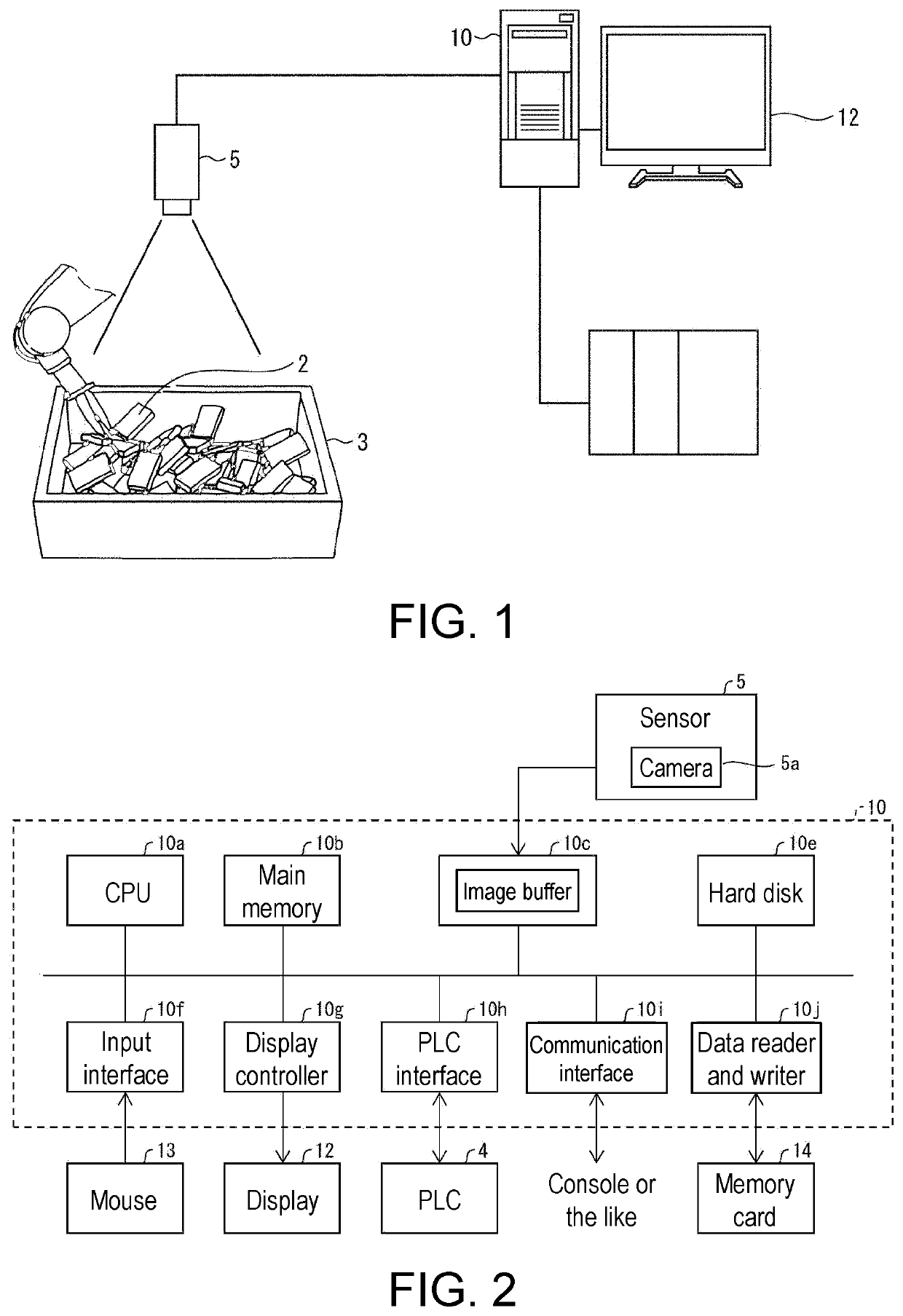
[0019]First, an example of a scene in which the invention is applied will be described with reference to FIG. 1. FIG. 1 is a diagram illustrating an overview of a system environment in which the target object recognition device 10 according to the embodiment is used. The target object recognition device 10 is a device that is used to recognize a state of a plurality of target objects 2 that are gripped and conveyed by a robot arm 50.

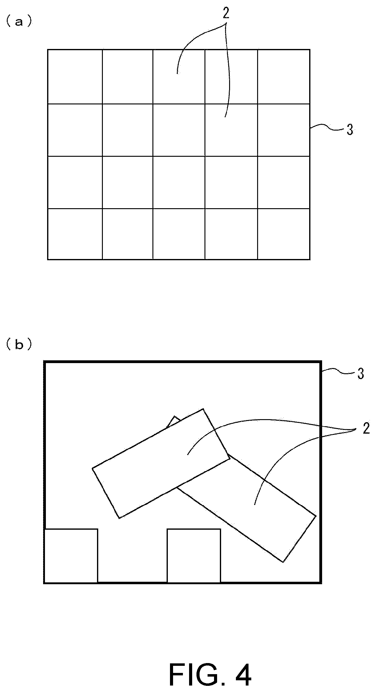
[0020]The plurality of target objects 2 are placed in a prescribed space region defined by, for example, a container 3 or a pallet. The target object recognition device 10 recognizes a layout state of the target objects 2 in the prescribed space region by referring to sensor information acquired from a sensor 5.

[0021]Further, the target object recognition device 10 includes a plurality of calculation processing units that calculate the attitude state of the target objects 2 in the prescribed space region, and a method for using cal...

embodiment 1

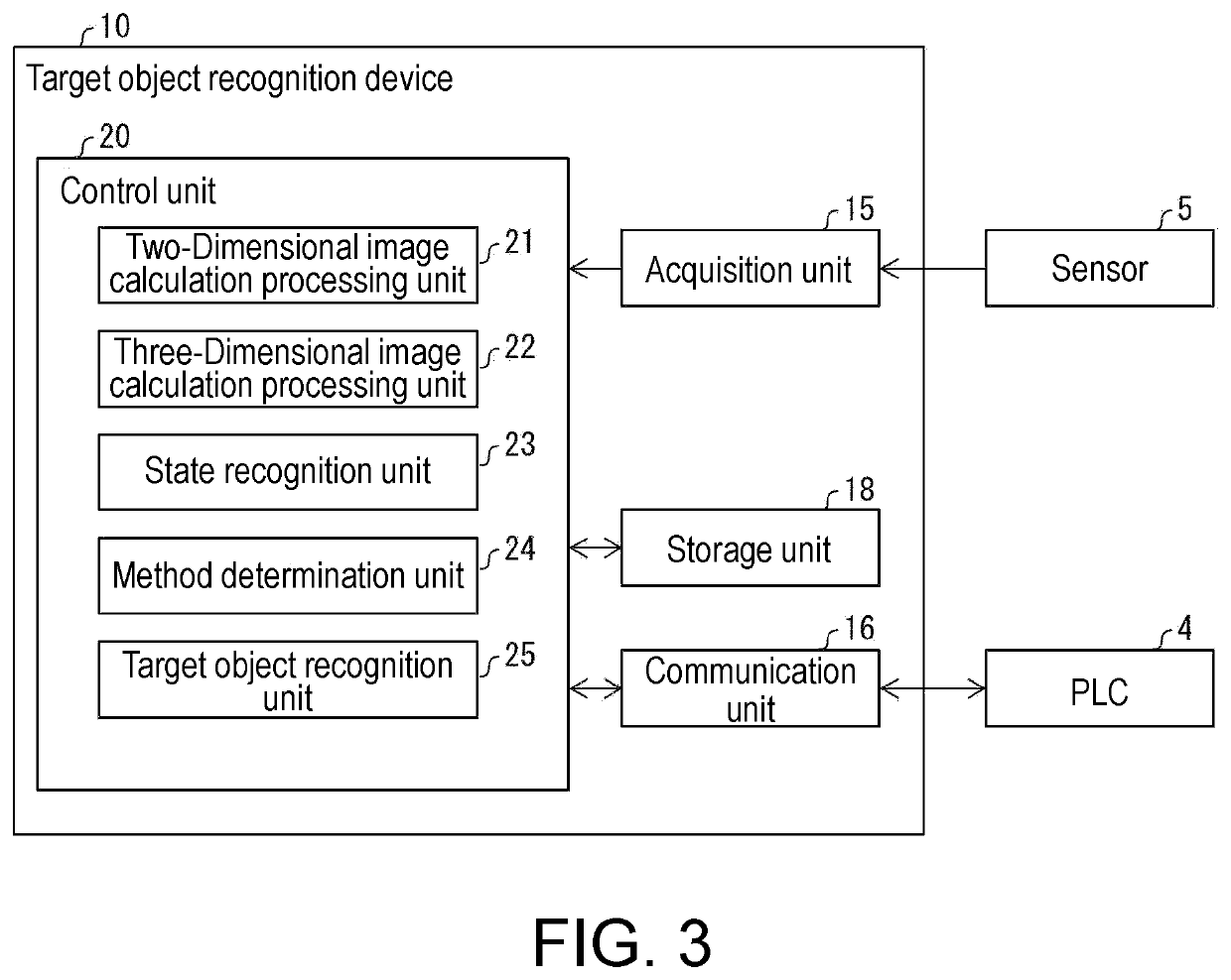
[0024]Hereinafter, a configuration of the target object recognition device 10 according to Embodiment 1 of the invention will be described in detail with reference to FIGS. 1, 2, and 3. FIG. 1 is a diagram schematically illustrating a schematic configuration of the target object recognition device 10. FIG. 2 is a hardware configuration diagram of the target object recognition device 10. FIG. 3 is a block diagram illustrating a main configuration of the target object recognition device 10.

[0025]As illustrated in FIG. 1, the target object recognition device 10 is connected to the sensor 5 and a programmable logic controller (PLC) 4. The target object recognition device 10 acquires sensor information from the sensor 5. Further, the target object recognition device 10 provides the PLC 4 with information corresponding to the sensor information acquired from the sensor 5. Although one sensor 5 is illustrated in FIG. 1, a plurality of sensors 5 may be connected to the target object recogni...

embodiment 2

[0083]Hereinafter, Embodiment 2 of the invention will be described. For convenience of description, members having the same functions as the members described in Embodiment 1 are denoted by the same reference numerals, and description thereof is not repeated.

[0084]FIG. 6 is a block diagram illustrating a main configuration of the manipulator 120 and the mobile robot 100 including the manipulator 120 according to Embodiment 2. FIG. 7 is a perspective view illustrating an external configuration of the mobile robot 100.

[0085]As illustrated in FIGS. 6 and 7, the manipulator 120 includes the robot arm 50, the target object recognition device 10, and the robot control unit 55 (control unit).

[0086]The robot arm 50 performs a gripping operation on the target objects 2 arranged in the container 3. The sensor 5 is provided, for example, in the vicinity of a gripping part that grips the target object 2 in the robot arm 50.

[0087]The robot control unit 55 controls the operation of the robot arm ...


PUM


Abstract

Provided is art capable of recognizing the states of a plurality of target objects arranged in a prescribed space region. This target object recognition device is provided with: a plurality of calculation processing units (21, 22) which each calculate the attitude state of a target object in a prescribed space region using a different technique; a state recognition unit (23) which recognizes the layout state of all of a plurality of target objects arranged in the space region; a method determination unit (24) which, in accordance with the result of the recognition by the state recognition unit (23), determines a method for using the results of the calculation performed by the calculation processing units (21, 22); and a target object recognition unit (25) which recognizes the attitude states of the target objects by means of the determined method for using the results of the calculation.

Description

TECHNICAL FIELD[0001]The invention relates to a target object recognition device, a manipulator, and a mobile robot.RELATED ART[0002]In the related art, technologies of gripping and conveying a plurality of workpieces loaded adjacent to each other by picking workpieces with a robot are known. In these technologies, a position of a workpiece is taught to a robot in advance and the workpiece is arranged at the taught position so that the robot can pick the workpiece. On the other hand, when positions at which a plurality of workpieces are arranged are misaligned or when a plurality of loaded workpieces collapses and is put into a bulk state, the robot cannot pick the respective workpieces.[0003]Therefore, a technology for detecting an edge portion of each workpiece from an entire image captured by photographing a plurality of loaded workpieces, recognizing a position and attitude of each workpiece with the edge portion as a boundary, and picking up the workpieces with a robot has been...

Claims


Application Information

Patent Timeline
Patent Type & Authority Applications(United States)
IPC IPC(8): B25J9/16G06T7/73G06T7/13
CPCB25J9/1697G06T7/73G06T2207/30164G06T2207/20081G06T7/13B25J5/007G06T7/74G06T7/001G06T2207/10012G06T2207/20084B25J9/163G05B2219/40053G05B2219/40014G05B2219/39484G05B2219/40532
Inventor KONISHI, YOSHINORIKOGA, TATSUYA
Owner ORMON CORP
Features
  • R&D
  • Intellectual Property
  • Life Sciences
  • Materials
  • Tech Scout
  • Unparalleled Data Quality
  • Higher Quality Content
  • 60% Fewer Hallucinations
Learn More