Flexible installation of a hydrocarbon liquefaction unit

a hydrocarbon liquefaction and installation technology, which is applied in the direction of refrigeration and liquifaction, lighting and heating equipment, solidification, etc., can solve the problems of large societal risk, large available land, and high environmental restrictions, so as to reduce mechanical effects, reduce ground footprint, and limit thermal losses

Pending Publication Date: 2021-10-07
LAIR LIQUIDE SA POUR LETUDE & LEXPLOITATION DES PROCEDES GEORGES CLAUDE
View PDF5 Cites 0 Cited by
  • Summary
  • Abstract
  • Description
  • Claims
  • Application Information

AI Technical Summary

Benefits of technology

[0051]The present invention will basically cover the cryogenic part of the method. It forms the liquefaction area thereof. In order to limit thermal losses, this part of the method is installed in an insulating box, called cold box. The temperatures vary between +20° C. to −196° C. The equipment is therefore subject to significant mechanical stresses. In order to reduce the mechanical effects, it is common to distribute the stresses over the whole of the relevant method line. The solution implemented in the present invention allows an approach for managing stresses to be provided by defining the cold box as being autonomous. The stresses inside the cold box will be managed by placing a fixed point at the limit of the cold box or by providing permissible stresses for other parts.
[0052]This installation allows the cold-part modules (heat-exchange module and separator module) to be aligned together and allows the hot part (compressor module) to be added in line with or perpendicular to this alignment, thus reducing the ground footprint and also reducing the lengths of the interconnections.

Problems solved by technology

The available land is generally small and must meet strict environmental restrictions.
However, their hazardousness results in factory configurations that are very spread out with a very high societal risk.

Method used


Image

  • Flexible installation of a hydrocarbon liquefaction unit

Examples


Embodiment Construction

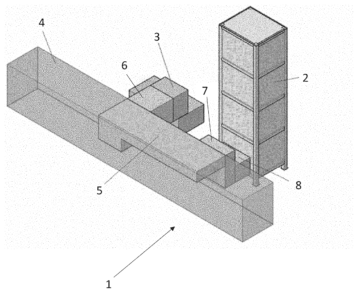
[0056]FIG. 1 shows a representation of a schematic diagram of a liquefaction unit according to one embodiment of the invention.

[0057]In FIG. 1, the hydrocarbon fluid liquefaction unit 1 comprises:[0058]at least one cryogenic cold box 2 comprising:[0059]at least one heat exchanger;[0060]a fixed assembly zone 8 on its outer wall;[0061]a device 3 for the various equipment required for implementing the cold fluid required for the liquefaction of a natural gas stream from a hydrocarbon supply stream;[0062]an interconnection module 4 comprising a pipe holder means and a set of pipes, control valves, and electricity connection and instrumentation 5, 6, 7, designed to connect said at least one cold box 2 to the at least one equipment device 3 for the cycle for refrigerating and / or separating C6+ type hydrocarbon elements contained in the natural gas.

[0063]The interconnection module 4 rests on a frame that allows it to be handled and is connected to the cold box in the vicinity of said assem...


PUM


Abstract

Natural gas liquefaction unit including at least one cryogenic cold box having at least one heat exchanger; a fixed assembly zone on its outer wall; at least one closed loop nitrogen refrigeration cycle; at least one device for equipment required for implementing the liquefaction of a natural gas stream from a hydrocarbon supply stream; at least one interconnection module comprising a pipe holder means and a set of pipes and valves, designed to connect said at least one cold box to at least one equipment device for the cycle for refrigerating and/or separating C6+ type hydrocarbon elements contained in the natural gas, wherein the interconnection module rests on a frame allowing it to be handled and is connected to the cold box and to the other method or equipment sub-assemblies located around said fixed assembly zone.

Description

CROSS REFERENCE TO RELATED APPLICATIONS[0001]This application claims the benefit of priority under 35 U.S.C. § 119 (a) and (b) to French Patent Application No. 2003456, filed Apr. 7, 2020, the entire contents of which are incorporated herein by reference.FIELD OF THE INVENTION[0002]The technical field of the invention is that of the liquefaction of natural gas using a nitrogen refrigeration cycle.[0003]The present invention relates to an installation of a natural gas liquefaction unit using a nitrogen refrigeration cycle and its unit.BACKGROUND OF THE INVENTION[0004]Natural gas liquefaction methods need to be used in order to reduce the environmental impact. Market developments promote the use of liquefiers close to public areas in order to ensure more efficient management of deliveries. The available land is generally small and must meet strict environmental restrictions.[0005]Commonly, this type of unit uses mixed coolants that are mixtures of gas with high yields for the liquefac...

Claims


Application Information

Patent Timeline
Patent Type & Authority Applications(United States)
IPC IPC(8): F25J1/02F25J1/00F25J3/02
CPCF25J1/0238F25J1/0022F25J3/0247F25J1/0222F25J2240/40F25J2230/24F25J2230/32F25J2230/60F25J1/0259F25J1/0072F25J1/005F25J1/0204F25J1/0288F25J2270/16
Inventor FARGES, ORIANEPLAMONDON, YOLANDSZAMLEWSKI, CHRISTOPHE
Owner LAIR LIQUIDE SA POUR LETUDE & LEXPLOITATION DES PROCEDES GEORGES CLAUDE
Why Eureka
Try Eureka