Household cooking hob

Pending Publication Date: 2021-10-07
ELECTROLUX APPLIANCES
View PDF0 Cites 0 Cited by
  • Summary
  • Abstract
  • Description
  • Claims
  • Application Information

AI Technical Summary

Benefits of technology

[0056]A person skilled in the art will immediately understand that the heat, generated by and / or radiated from particularly the heating power transferring elements, the heating power energy unit and / or the cookware item, particularly the bottom thereof, may have also disadvantageous effects, particularly regarding safety and proper functioning. Particularly, the heating power energy unit, more particularly power circuits comprising switching elements, may generate a significant amount of heat being disadvantage for the safety and proper functioning of the cooking hob. For this reason, the cooking hob comprises at least one cooling means. Particularly, said cooling means is adapted for cooling down the electric and / or electronic elements. Particularly, the heating power energy unit may comprise such cooling means. Such cooling means may comprise at least one of a fan, a cooling channel, a cooling body, preferably from a metal, particularly aluminium, cooling air-guiding means, cooling air deflection means and the like. Particularly, the cooking hob of the present invention may comprise such cooling means for cooling at least one heating power generator or a part thereof, particularly to at least one single or pair of high frequency switching elements. More particularly, such cooling means may comprise a cooling body, preferably arranged in the air path of a cooling fan, and thermally connected to at least one heating power generator or a part thereof, particularly to at least one single or pair of high frequency switching elements. Thereby it is preferred that the cooling means comprises at least one fan for generating an air stream through the cooling channel. Preferably, the cooling channel and / or cooling body extends horizontally through the cooking hob. For example, the cooling channel and / or cooling body extends over a substantial part of the horizontal width of the cooking hob.
[0057]The cooking hob according to the present invention preferably further comprises a control unit, in the following also referred to as control entity. Such control unit is preferably operatively connected with the heating power energy unit to control at least one operational parameter of the cooking hob, particularly an operational parameter of the heating power energy unit. Furthermore, the control unit comprises a user interface at least for receiving a command input of a user. This advantageously allows the user to control at least one operational parameter of the cooking hob, particularly an operational parameter of the heating power energy unit. Moreover, the control unit, and particularly a user interface if present, may be operatively connected to other appliances or interfaces, e.g. a suction hood, a voice control device, a server, a remote interface, a cloud-computing source or the like.
[0058]Accordingly, the household cooking hob according to the present invention comprises at least one electric and / or electronic element. Particularly, said at least one electric and / or electronic element comprises a heating power energy unit and / or control unit or parts thereof.
[0059]Particularly, the at least one electric and / or electronic element of the household cooking hob of the present invention may be part of an at least one heating energy power unit, preferably mounted and / or arranged on a power board and / or a power generating circuit mounted on a printed circuit board (PCB).
[0060]Such at least one electric and / or electronic element may be, for example, selected from the group comprising a heating power generator, filter coils, EMC filters, rectifier, switching elements, like IGBTs, relays, or the like.

Problems solved by technology

Disadvantageously, known cooking hobs comprise a complex circuitry for controlling the cooking process based on a plurality of temperature detecting parts.

Method used


Image

  • Household cooking hob

Examples


Embodiment Construction

[0065]The present invention will now be described more fully with reference to the accompanying drawings, in which example embodiments are shown. However, this invention should not be construed as limited to the embodiments set forth herein. Throughout the following description similar reference numerals have been used to denote similar elements, parts, items or features, when applicable.

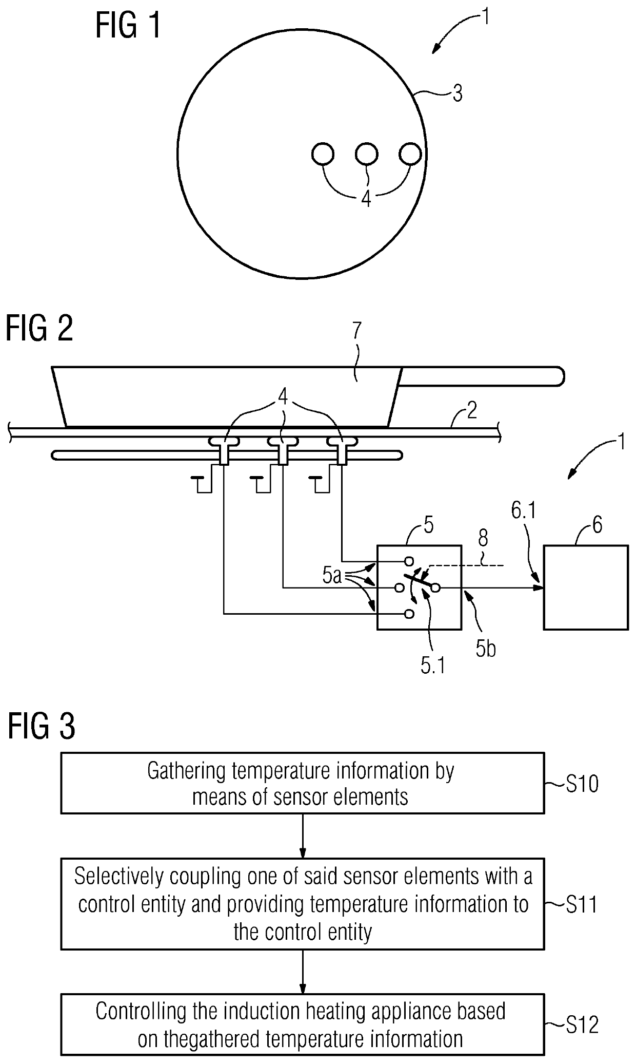
[0066]FIG. 1 illustrates a top view on a schematic illustration of an induction heating appliance 1 comprising an induction coil 3 and a set of sensor elements 4. In the present example, three sensor elements 4 are shown. However, the present disclosure should be not considered limited to such number of sensor elements 4. In general, the induction heating appliance 1 may comprise two or more sensor elements 4. The sensor elements 4 are associated with the induction coil 3 such that all sensor elements 4 are distributed over an area covered by the induction coil 3. More specifically, the sensor eleme...


PUM


Abstract

The invention relates to a household cooking hob, particularly to an induction heating hob comprising a cooking surface (2) and a heating power transferring element, particularly an inductor or induction coil (3) preferably provided below the cooking surface (2), wherein at least two sensor elements (4) are distributed in an area covered by the heating power transferring element (3), the sensor elements (4) being configured to gather information regarding the temperature of a piece of cookware placed on the cooking surface (2), wherein an electrical circuit (5) is provided which comprises switching means (5.1) for providing a selective electrical coupling of one of said sensor elements (4) with a control entity (6).

Description

[0001]The present invention relates generally to the field of cooking hobs, in particular household or domestic cooking hobs. More specifically, the present invention relates to a cooking hob comprising multiple spatially distributed sensor elements for controlling the operation of the cooking hob.BACKGROUND OF THE INVENTION[0002]Cooking hobs, particularly induction hobs, per se, are known in the prior art.[0003]Document JP 2003317919 A discloses an induction heating cooking device. The induction heating cooking device comprises a plurality of temperature detecting parts.[0004]Disadvantageously, known cooking hobs comprise a complex circuitry for controlling the cooking process based on a plurality of temperature detecting parts.SUMMARY OF THE INVENTION[0005]It is an objective of the embodiments of the invention to provide a cooking hob with reduced technical effort which can therefore be manufactured with reduced costs. The objective is solved by the features of the independent cla...

Claims


Application Information

Patent Timeline
Patent Type & Authority Applications(United States)
IPC IPC(8): H05B6/06
CPCH05B6/062H05B2213/07
Inventor VIROLI, ALEXJEANNETEAU, LAURENT
Owner ELECTROLUX APPLIANCES
Why Eureka
Try Eureka