Microwave generation

a technology of apparatus and methods, applied in the direction of pulse generation by energy-accumulating elements, transit-tube circuit elements, therapy, etc., can solve the problems of instabilities in the operation of the microwave generator, degrade the quality of the microwave output,

Inactive Publication Date: 2020-11-12
E2V TECH (UK) LTD
View PDF0 Cites 0 Cited by
  • Summary
  • Abstract
  • Description
  • Claims
  • Application Information

AI Technical Summary

Benefits of technology

[0041]The semiconductor switch may comprise a solid state field effect transistor (FET) or an insulated-gate bipolar transistor (IGBT).

Problems solved by technology

Reducing or increasing the power which is provided to the microwave generator away from the operating power level for which the modulator and microwave generator are optimised, can lead to disadvantageous effects which degrade the quality of the microwaves output from the microwave generator and / or cause instabilities in the operation of the microwave generator.

Method used


Image

  • Microwave generation
  • Microwave generation
  • Microwave generation

Examples


first embodiment

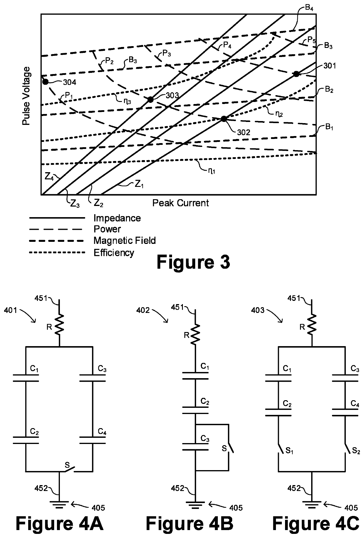
[0132]the impedance network 401, which is shown in FIG. 4A, includes a first capacitor C1, a second capacitor C2, a third capacitor C3 and a fourth capacitor C4. The first C1 and second C2 capacitors are provided in a first electrical pathway extending between the first connection 451 and the second connection 452. The third C3 and fourth C4 capacitors are provided in a second electrical pathway extending between the first connection 451 and the second connection 452. The second electrical pathway includes a switch S. The switch S is operable to be opened and closed so as to disconnect and connect the second electrical pathway.

[0133]When the switch S is opened, the capacitance and therefore the impedance between the first connection 451 and the second connection 452 is determined by the first C1 and second C2 capacitors only. When the switch S is closed, the capacitance and therefore the impedance between the first connection 451 and the second connection 452 is determined by the pa...

second embodiment

[0134]the impedance network 402, which is shown in FIG. 4B, includes a first capacitor C1, a second capacitor C2 and a third capacitor C3 connected in series with each other in between the first connection 451 and the second connection 452. A switch S is connected across the third capacitor C3. The switch S is operable to be opened in order to include the third capacitor C3 in the electrical pathway between the first connection 451 and the second connection 452. The switch S is further operable to be closed in order to provide a short circuit around the third capacitor C3. That is, opening and closing the switch S disconnects and connects a short circuit around the third capacitor C3.

[0135]When the switch S is opened, the capacitance and therefore the impedance between the first connection 451 and the second connection 452 is determined by the series capacitance and impedance of the first C1, second C2 and third C3 capacitors. When the switch S is closed, the capacitance and therefo...

third embodiment

[0136]the impedance network 403, which is shown in FIG. 4C, includes a first capacitor C1, a second capacitor C2, a third capacitor C3 and a fourth capacitor C4. The first C1 and second C2 capacitors are provided in a first electrical pathway extending between the first connection 451 and the second connection 452. The third C3 and fourth C4 capacitors are provided in a second electrical pathway extending between the first connection 451 and the second connection 452. The first electrical pathway includes a first switch S1 and the second electrical pathway includes a second switch S2. The first S1 and second S2 switches are operable to be opened and closed so as to disconnect and connect the first and second electrical pathways respectively.

[0137]The first S1 and second S2 switches S1 provide three different switching combinations such that the capacitance and impedance provided between the first connection 451 and the second connection 452 may be switched between three different va...


PUM

PropertyMeasurementUnit
powersaaaaaaaaaa
peak powersaaaaaaaaaa

Abstract

A microwave generation system comprising a microwave generator, a pulse generator and an impedance network. The pulse generator is arranged to provide pulses of electrical power to the microwave generator and is operable to vary the power of the pulses of electrical power which are provided to the microwave generator. The impedance network is connected between the pulse generator and the microwave generator. The impedance network is switchable so as to substantially match an impedance across the pulse generator according to variations in the impedance of the microwave generator.

Description

FIELD OF THE INVENTION[0001]The present disclosure relates to apparatus and methods for the generation of microwaves. The apparatus and methods may find particular application but not exclusively in the field of the generation of microwaves for use in a particle accelerator.BACKGROUND[0002]A microwave generator such as a magnetron or a klystron may be used to generate microwaves for a variety of different purposes. For example, microwaves generated by a microwave generator may be provided to a particle accelerator (such as a linear accelerator) and used to establish accelerating electromagnetic fields for the acceleration of charged particles, such as electrons. In some applications accelerated electrons may be directed to be incident on a target material (such as tungsten), which causes some of the energy of the electrons to be emitted as x-rays from the target material.[0003]Generated X-rays may, in some applications, be used for medical imaging and / or treatment purposes. For exam...

Claims


Application Information

Patent Timeline
Patent Type & Authority Applications(United States)
IPC IPC(8): H03H7/38H03K3/57H01J25/587
CPCH01J25/587H03K3/57H03H7/38A61N2005/1089H01J23/34H05H7/02H05H2007/022H05H2007/027H05H2277/11A61N5/10A61N2005/1022H01J23/16H01J23/36H03K3/53H03K3/80
Inventor ISKANDER, MARKROWLANDS, DAVID
Owner E2V TECH (UK) LTD
Why Eureka
Try Eureka