Spin cleaning method and apparatus for additive manufacturing

a technology of additive manufacturing and spin cleaning, which is applied in the direction of chemistry apparatus and processes, cleaning using liquids, manufacturing tools, etc., can solve the problems of large amount of wash liquids and generally slow techniques, and achieve the effect of reducing the viscosity and reducing the viscosity of liquids

Pending Publication Date: 2021-10-21
SAMSUNG ELECTRONICS CO LTD
View PDF4 Cites 4 Cited by
  • Summary
  • Abstract
  • Description
  • Claims
  • Application Information

AI Technical Summary

Benefits of technology

[0016]In some embodiments, the method further includes warming the excess resin sufficiently to reduce the viscosity thereof during the centrifugally separating step.
[0017]In some embodiments, the method further includes applying a solvent (e.g., by spraying) to the excess resin in an amount sufficient to reduce the viscosity thereof during the centrifugally separating step.

Problems solved by technology

Stereolithography resins—both conventional and dual cure—are generally viscous, and excess, unpolymerized, resins adhere to objects after they have been produced.
No. 2017 / 0173872), but such techniques are generally slow, are not adapted for high through-put manufacturing situations, may require large amounts of wash liquids, and—because the excess resin is carried away in the wash liquid—generally preclude collection and use of the excess resin in subsequent stereolithographic production steps.

Method used


Image

  • Spin cleaning method and apparatus for additive manufacturing
  • Spin cleaning method and apparatus for additive manufacturing
  • Spin cleaning method and apparatus for additive manufacturing

Examples


Embodiment Construction

[0046]The present invention is now described more fully hereinafter with reference to the accompanying drawings, in which embodiments of the invention are shown. This invention may, however, be embodied in many different forms and should not be construed as limited to the embodiments set forth herein; rather these embodiments are provided so that this disclosure will be thorough and complete and will fully convey the scope of the invention to those skilled in the art.

[0047]Like numbers refer to like elements throughout. In the figures, the thickness of certain lines, layers, components, elements or features may be exaggerated for clarity.

[0048]The terminology used herein is for the purpose of describing particular embodiments only and is not intended to be limiting of the invention. As used herein, the singular forms “a,”“an” and “the” are intended to include plural forms as well, unless the context clearly indicates otherwise. It will be further understood that the terms “comprises...


PUM

PropertyMeasurementUnit
viscosityaaaaaaaaaa
viscosityaaaaaaaaaa
viscosityaaaaaaaaaa

Abstract

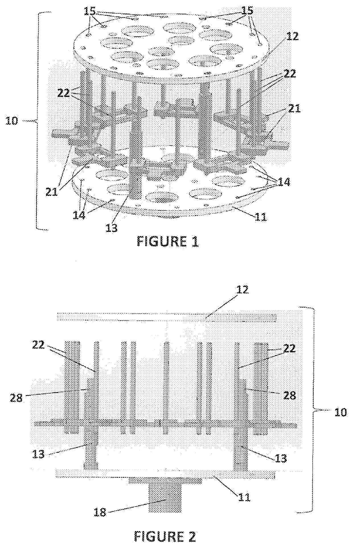
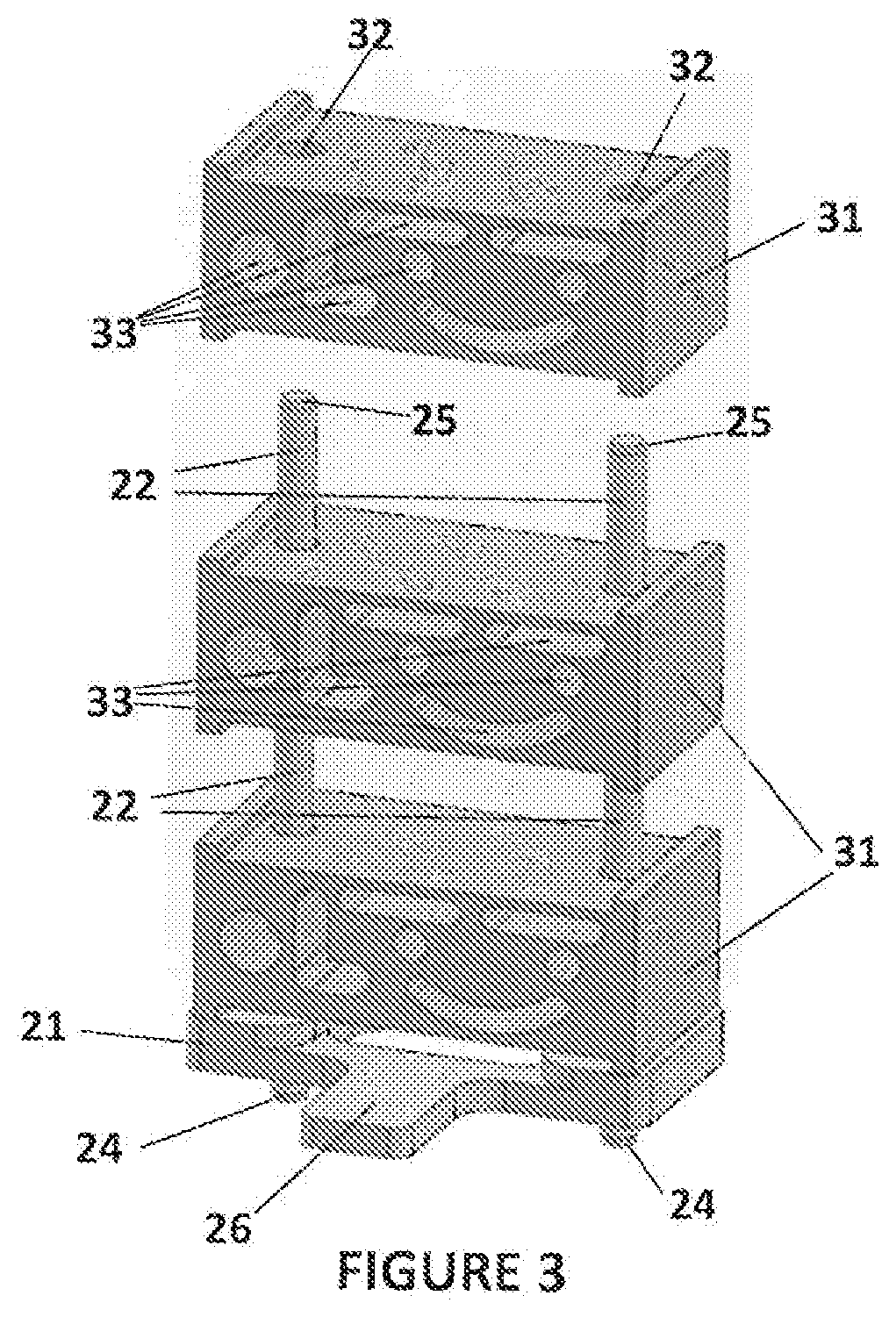
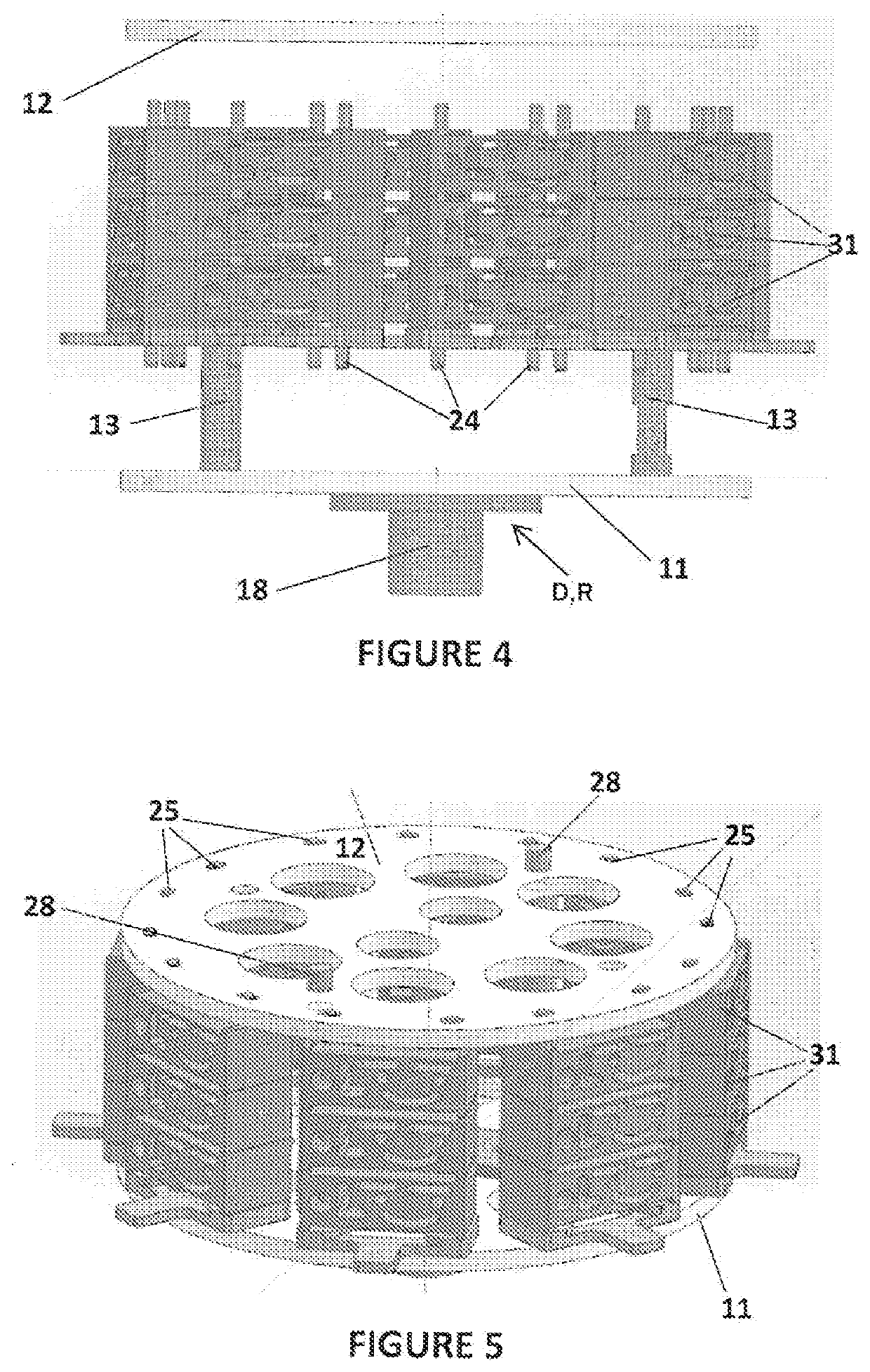
A method of separating excess resin from at least one object includes: (a) stereolithographically producing at least one object, each object having at least one retention feature (32) formed thereon, each object carrying excess resin on a surface thereof; then (b) mounting each object on at least one transfer frame (21), each transfer frame having at least one retention member (22) that mates with the retention feature; (c) connecting each transfer frame to a rotor with the at least one object carried thereon; (d) centrifugally separating excess resin from each object by spinning the rotor with each transfer frame connected thereto while the at least one object remains connected to each transfer frame by the retention feature; then (e) removing each transfer frame from the rotor, with excess resin separated from each at least one object thereon.

Description

RELATED APPLICATIONS[0001]This application claims priority from U.S. Provisional Application No. 62 / 736,648, filed Sep. 26, 2018, the disclosure of which is hereby incorporated by reference herein in its entirety.FIELD OF THE INVENTION[0002]The present invention concerns methods of additive manufacturing, and particularly concerns methods of extracting or removing excess resin from objects following their production by top-down or bottom-up stereolithography.BACKGROUND OF THE INVENTION[0003]A group of additive manufacturing techniques sometimes referred to as “stereolithography” create a three-dimensional object by the sequential polymerization of a light polymerizable resin. Such techniques may be “bottom-up” techniques, where light is projected into the resin onto the bottom of the growing object through a light transmissive window, or “top down” techniques, where light is projected onto the resin on top of the growing object, which is then immersed downward into a pool of resin.[...

Claims


Application Information

Patent Timeline
Patent Type & Authority Applications(United States)
IPC IPC(8): B29C64/35B33Y40/20B33Y30/00B29C64/357B08B7/02B08B7/00B08B3/08B08B7/04
CPCB29C64/35B33Y40/20B33Y30/00B29C64/357B29C64/129B08B7/0071B08B3/08B08B7/04B08B7/02B29C64/124B08B3/02B29C71/0009B29C2071/0027B29C2071/0045B33Y10/00B08B2220/04
Inventor DAY, ANANDA ROSEKWOK, KENTON J.TUCKER, WILLIAM JAMES
Owner SAMSUNG ELECTRONICS CO LTD
Why Eureka
Try Eureka