Communication control device and transceiver for a user station of a serial bus system, and method for communicating in a serial bus system

Inactive Publication Date: 2021-10-28
ROBERT BOSCH GMBH
View PDF0 Cites 1 Cited by
  • Summary
  • Abstract
  • Description
  • Claims
  • Application Information

AI Technical Summary

Benefits of technology

[0007]An object of the present invention is to provide a communication control device and a transceiver for a user station of a serial bus system, and a method for communicating in a serial bus system, which solve the above-mentioned problems. In particular, the present invention provide

Problems solved by technology

For example, if the edge steepness of the bits of the received signal is too low, this may result in bits with excessive asymmetry, and therefore the received signal may possibly not be decoded correctly.
Increasing the edge steepness of the bits

Method used


Image

  • Communication control device and transceiver for a user station of a serial bus system, and method for communicating in a serial bus system
  • Communication control device and transceiver for a user station of a serial bus system, and method for communicating in a serial bus system
  • Communication control device and transceiver for a user station of a serial bus system, and method for communicating in a serial bus system

Examples


Embodiment Construction

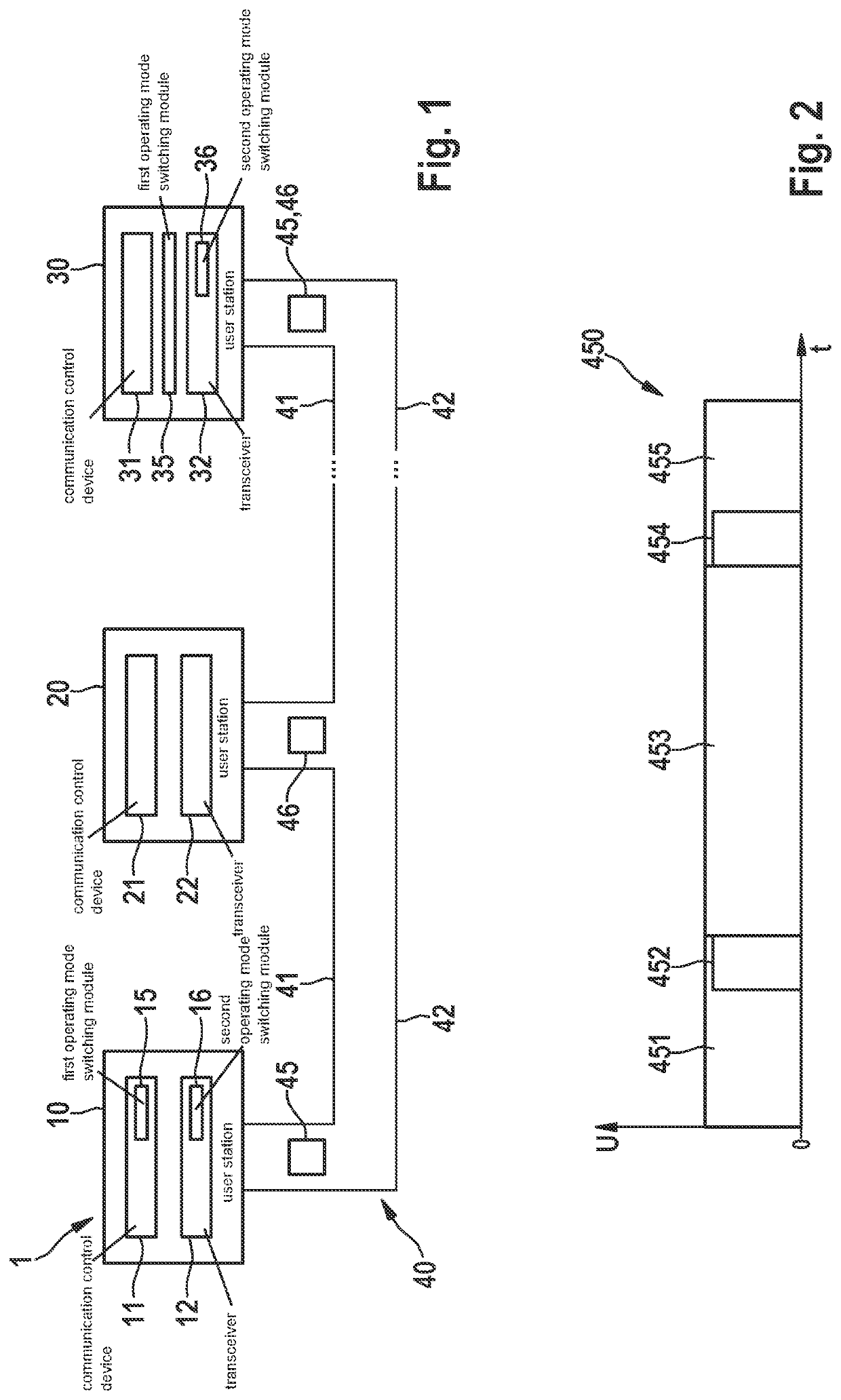
[0042]FIG. 1 shows as an example a bus system 1 that is in particular the basis for the design of a CAN bus system, a CAN FD bus system, a CAN FD successor bus system, and / or modifications thereof, as described below. The CAN FD successor bus system is referred to below as CAN XL. Bus system 1 may be used in a vehicle, in particular a motor vehicle, an aircraft, etc., or in a hospital, and so forth.

[0043]In FIG. 1, bus system 1 includes a plurality of user stations 10, 20, 30, each of which is connected to a first bus wire 41 and a second bus wire 42 at a bus 40. Bus wires 41, 42 may also be referred to as CAN_H and CAN_L, and are used for electrical signal transmission after coupling in the dominant levels or generating recessive levels for a signal in the transmission state. Messages 45, 46 in the form of signals are serially transmittable between individual user stations 10, 20, 30 via bus 40. User stations 10, 20, 30 are, for example, control units, sensors, display devices, etc...


PUM


Abstract

A communication control device and a transceiver for a user station of a serial bus system and a method for communicating in a serial bus system. The communication control device includes a communication control module for generating a transmission signal for controlling a communication of the user station with another user station of the bus system, in which bus system at least one first communication phase and one second communication phase being used for exchanging messages between user stations of the bus system, a first terminal for transmitting the transmission signal to a transceiver designed to transmit the transmission signal onto a bus, a second terminal for receiving a digital reception signal from the transceiver, a bidirectional terminal, and an operating mode switching module for switching the transmission direction of the bidirectional terminal as a function of the operating mode of the transceiver in the second communication phase.

Description

CROSS REFERENCE[0001]The present application claims the benefit under 35 U.S.C. § 119 of German Patent Application No. DE 102020205268.9 filed on Apr. 27, 2020, which is expressly incorporated herein by reference in its entirety.FIELD[0002]The present invention relates to a communication control device and a transceiver for a user station of a serial bus system, and a method for communicating in a serial bus system that operates with a high data rate and a high level of error robustness.BACKGROUND INFORMATION[0003]For the communication between sensors and control units, for example in vehicles, a bus system is frequently used in which data are transmitted as messages under the ISO 11898-1:2015 standard, as a CAN protocol specification with CAN FD. The messages are transmitted between the bus users of the bus system, such as the sensor, control unit, transducer, etc.[0004]To allow data to be transmitted at a higher bit rate than with CAN, an option has been provided in the CAN FD mes...

Claims


Application Information

Patent Timeline
IPC IPC(8): G06F13/42G06F13/12G06F13/40H04L12/40
CPCG06F13/4282G06F13/124H04L2012/40215H04L12/40G06F13/4004H04L12/40013H04L12/40078H04L25/0272
Inventor MUTTER, ARTHURHARTWICH, FLORIANWALKER, STEFFEN
Owner ROBERT BOSCH GMBH
Why Eureka
Try Eureka